The "ultimate" Thinkpad
In 2019 I bought a Lenovo Thinkpad X230 with the intention of using it as cheap laptop for travel/home use. Being a X series thinkpad the construction quality was good, but the display was absolutely terrible – a 1366x768 TN panel.
Looking for a way to upgrade it, I fell into a rabbit hole; it turns out the X220/X230 series of Thinkpads has quite a cult following of hackers going to great lengths to get the most out of these machines. I understand why when looking at the more recent Thinkpads – the quality is declining rather sharply: no more replaceable or redundant batteries, worse cooling due to the race-to-the-bottom for chassis thickness.
This blog post contains nothing particularly new, but serves as a useful amalgamation of various related guides.
Replacing the worn keyboard/palm rest/battery
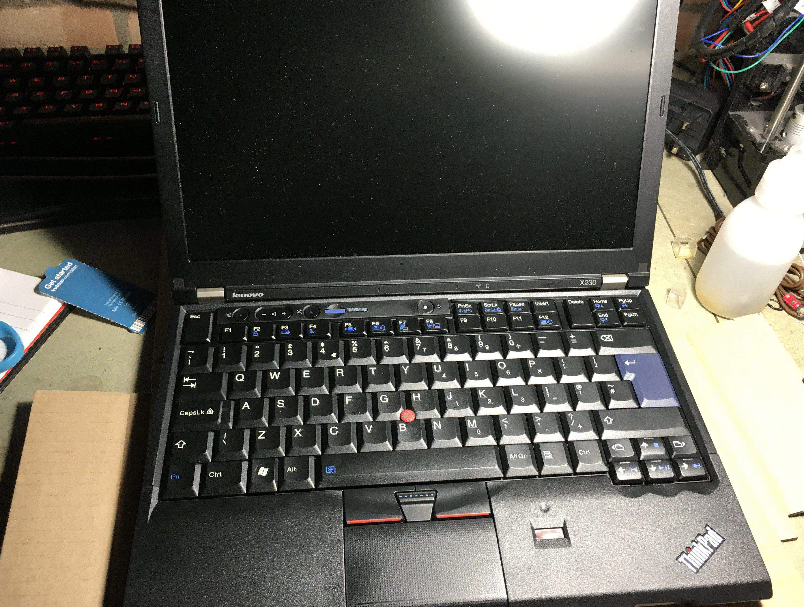
The first thing I wanted to do was to replace the keyboard and palm rest due to wear + general grease. Doing a bit of research I discovered, thanks to the work of Hamish Coleman it’s possible to replace the “modern” chicklet-style X230 keyboard with the classic 7-row X220 keyboard.
The X220 keyboard is not a drop in replacement – a simple modification has to be performed to the keyboard connector to mask off some conductors to prevent a short and resulting smoke. In addition, the embedded controller needs flashing with a hacked image to change the keyboard map without resorting to OS level software hacks. An X220 palm rest is also required, though it needs a small modification and also requires smaller screws; I found out the hard way after destroying the brass inserts…
See this guide for more information. Note that after applying the kapton tape, I found it was necessary to put a slice of thick paper in between the flex-PCB connector sandwich for a reliable connection.
Embedded controller hack
The embedded controller firmware image seems to be contained within the BIOS image; when a new BIOS image is flashed and that BIOS image contains a new EC (embedded controller) image, the next successful boot will cause the BIOS to flash the embedded controller.

In order to flash the embedded controller with a suitable new keymap, Thinkpad EC exists. It’s a simple makefile that automates the download/extraction/patch/bundle of the Thinkpad BIOS update program; it produces a bootable USB flash drive image. The scripts can also patch the EC such that it’s possible to use an aftermarket battery – I enabled this option out of principle, though beware that the quality and safety of 3rd-party batteries cannot be guaranteed. That said, my original 2012 battery that came with the Thinkpad was in good condition.
To create an image:
git clone https://github.com/hamishcoleman/thinkpad-ec.git
cd thinkpad-ec
make patch_enable_battery clean
make patched.x230.img
lsblk  # see what device name your flash drive has first, this case is sdb
umount /dev/sdb1  # undo the work of the automounter
sudo dd if=patched.x230.img of=/dev/sdb bs=8M status=progress
sync
Next, with the stock BIOS, boot the flash drive using F12 to bring up the boot selection menu. The program will ask for confirmation, copy the image and reboot; note that the embedded controller isn’t actually flashed until the BIOS decides to flash it.
The stock BIOS will only attempt to flash the EC if the battery and mains adapter are connected. Also, note that the clock must be set and there must be no CMOS checksum errors. When the machine is flashing the EX, the fan will ramp up and the screen will say so before restarting after a few dozen seconds.
Ultimately I reverted to the X230 keyboard as I wasn’t happy with the mechanical fit; however the X230 keyboard still had a bit of a misalignment at the bottom of the palm rest so I regretted the change back to the X230 keyboard…
Installing an IPS full HD panel
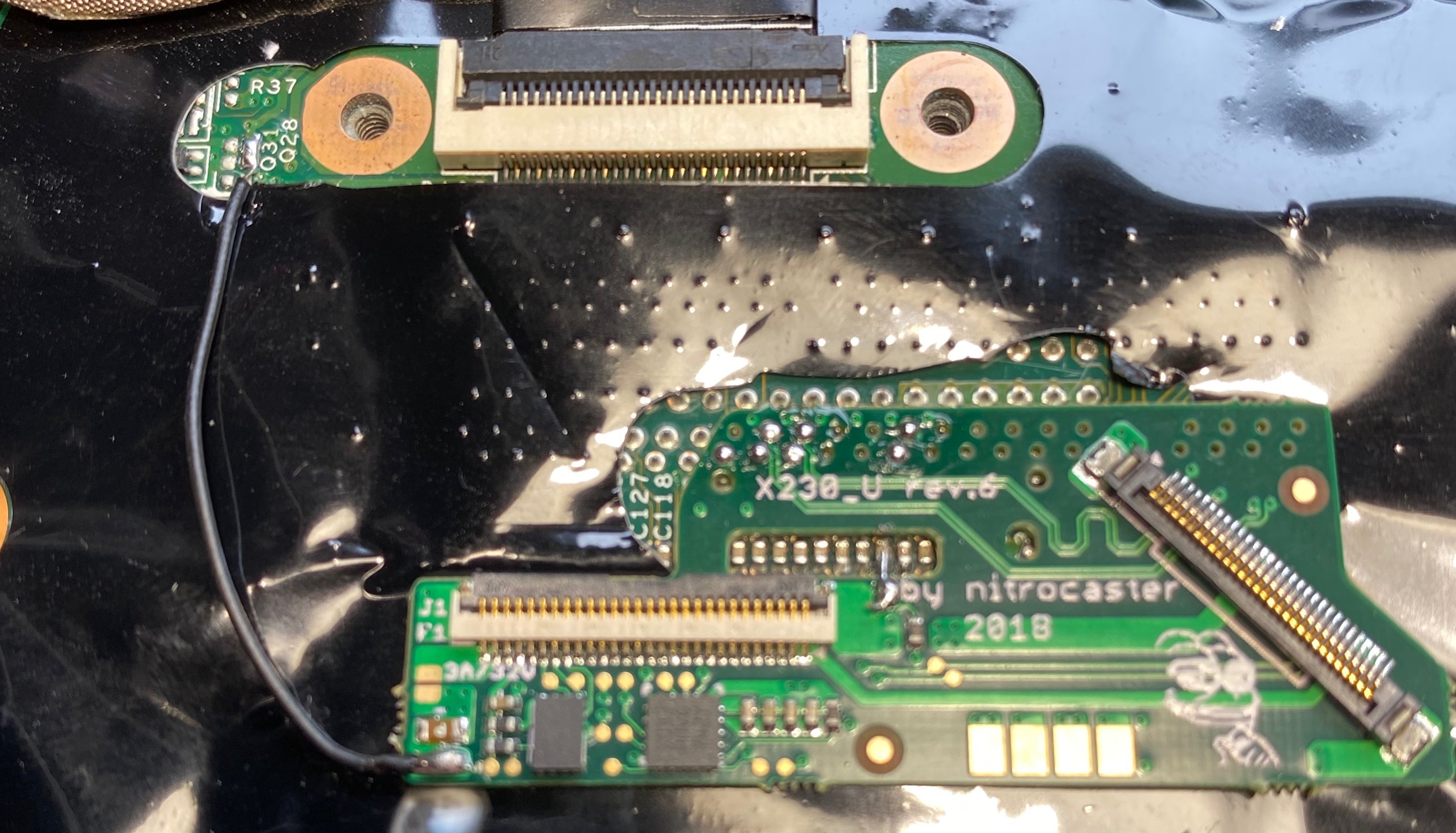
It’s possible to fit a 1920x1080 panel into an X220/X230 using an adapter board – in my case the Nitrocaster board. The adapter board replaces the LVDS screen interface (which does not have enough bandwidth for 1920x1080 at a decent frame rate) with lanes from the external display port connector. The board also routes the requisite signals for display sleep, backlight etc. A full schematic is even available!
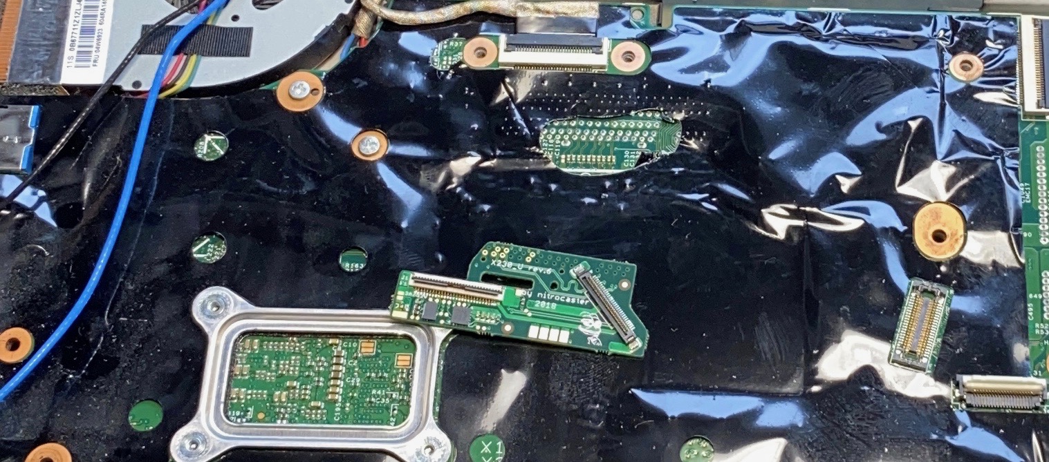
I won’t cover the installation steps as it’s covered by a fairly comprehensive guide already available here: https://nitrocaster.me/files/x220.x230_fhd_mod_rev5_v0.2.pdf.
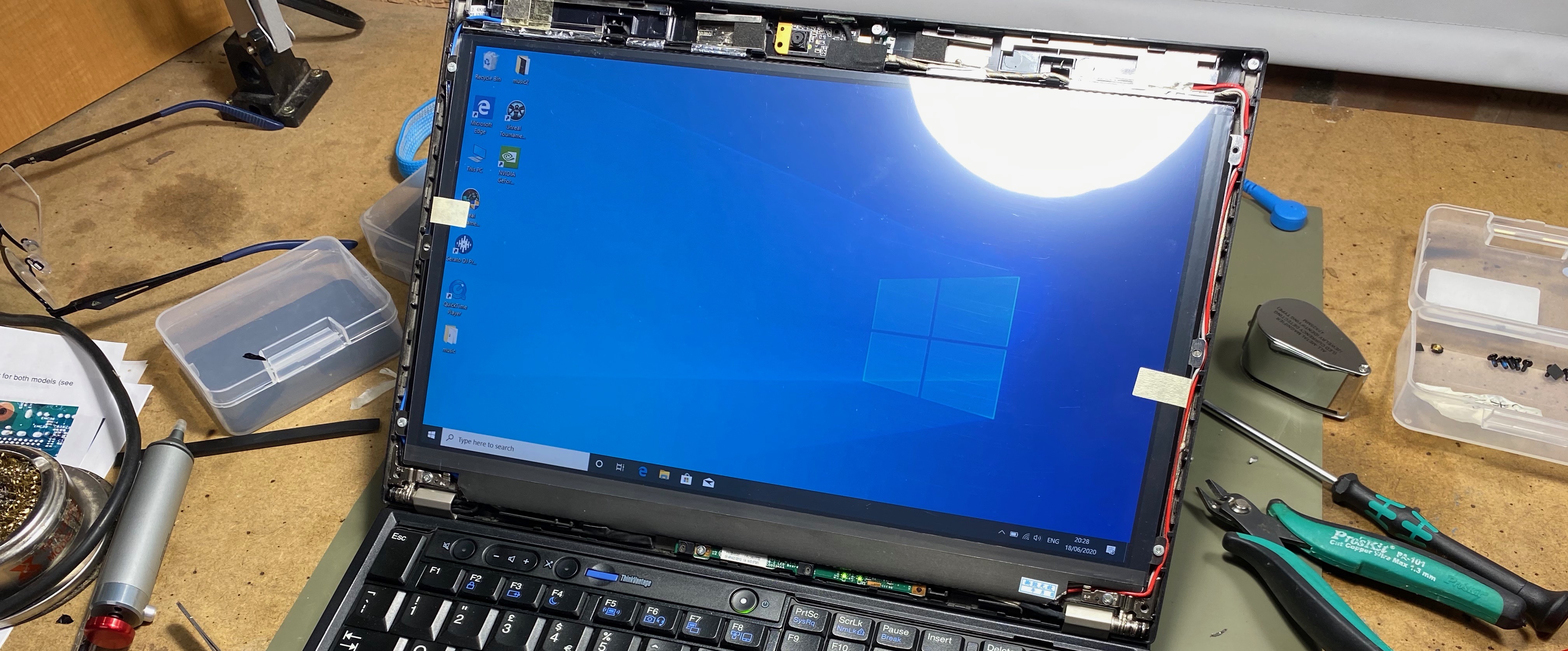
I installed a LG LP125WF2-SPB4 panel from Aliexpress. It is a matte model which makes it crisper and more viewable in sunlight; I don’t like the 15-year trend for glossy screens. The screen worked excellently.
Thankfully the panel worked first time, despite the use of my low-end Antec soldering iron; a soldering iron I recommend but not for fine soldering. For fine (and coarse) soldering I now have a Hakko FX-951 which is fantastic.
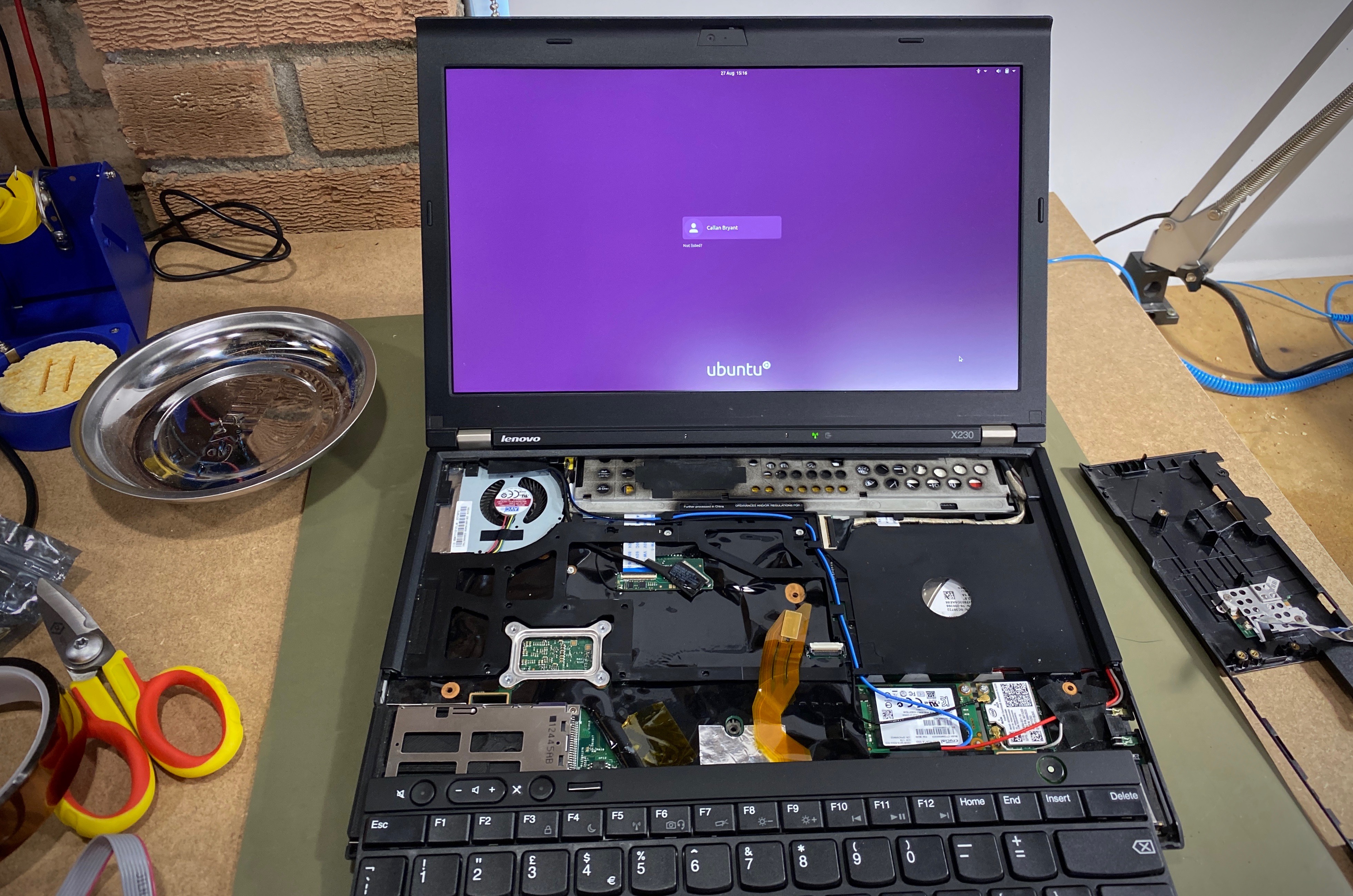
Installing a customised coreboot BIOS
After installing the Nitrocaster mod, I found that despite things working perfectly with Windows 10, Ubuntu 20.04 would see an extra phantom LVDS panel in addition to the main panel now connected via eDP. Unfortunately the LVDS panel is assumed to be the primary display so a blank image was shown on the login screen with Ubuntu. Kernel mods aside, it seems the only recourse was to flash the BIOS with a modified Coreboot install..
Coreboot is an open-source BIOS replacement with support for the X230. With this patch, it’s possible to remove the LVDS connection from the video bios table such that it’s no longer seen by Ubuntu.
Coreboot also has a few more benefits: the ability to disable the Intel backdoor management engine and a simplified implementation that only initialises hardware, passing execution to a payload that does the rest.
Here’s where it gets really involved – though there are many steps it’s all quite logical and straightforward; I was able to figure out what’s necessary between the (deprecated) coreboot documentation and a few helpful blog posts.
By far, the most useful guide I found was Chuck Nemeth’s. This section basically covers the same steps but with commentary.
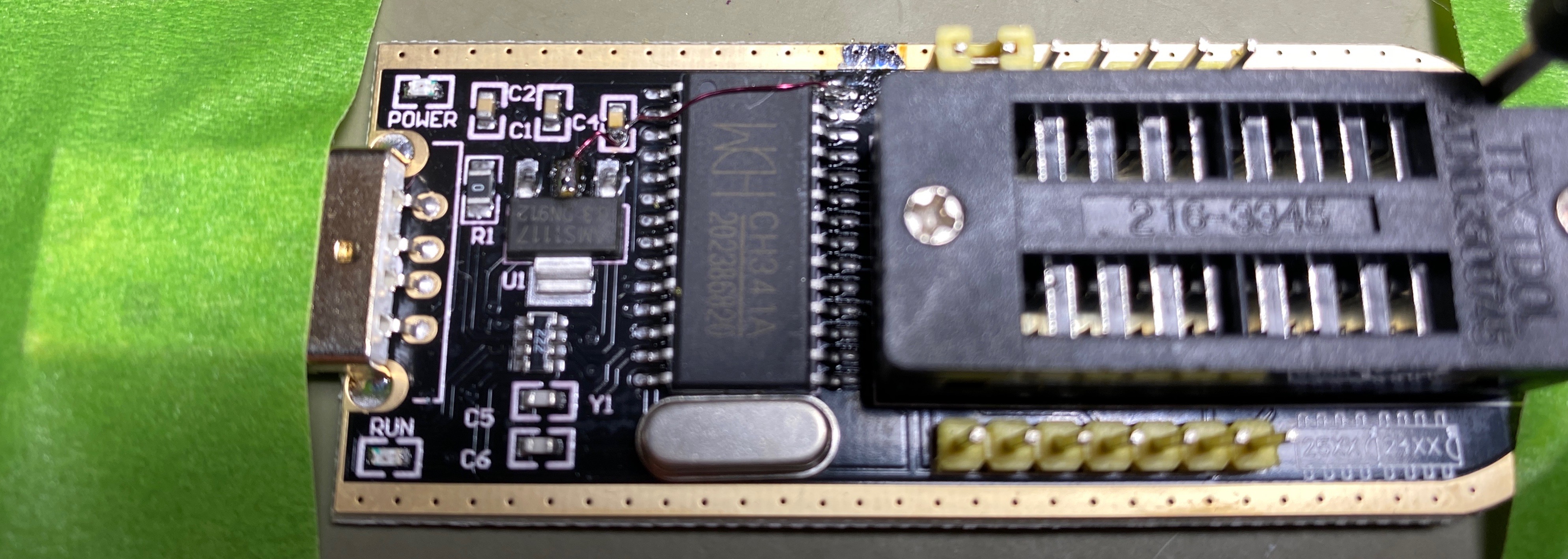
As Coreboot just deals with hardware initialisation, we still rely on some existing closed-source binary blobs to boot the Thinkpad. They have to be extracted and spliced into the resulting firmware image. To obtain them in the first place, the X230 stock BIOS has to be read from the 2 EEPROMs on the mainboard; a CH341A based EEPROM programmer can be used for this + the final writing.
Procedure summary
- Read existing stock BIOS image from the 2 EEPROMS
- Combine the EEPROM dumps to form the stock BIOS image
- Split the BIOS image to extract blobs: the BIOS itself, the Intel ME (management engine) image, the Gigabit ethernet firmware and the image descriptor.
- Download and configure coreboot (set to disable ME)
- Apply the Full HD patch (manually)1
- Copy the blobs to the coreboot tree
- Compile coreboot
- Split the resulting image into parts for each EEPROM
- Write the resulting image to the EEPROMS
CH341A programmer modification
I got a CH341A programmer, but was pleased to find the warning on Chuck’s article – the programmer I had was configured to operate at 5v instead of 3.3v; this is a problem as the EEPROMS are connected to a 3v3 rail inside the thinkpad and possibly aren’t 5v tolerant.2 The modification is simple – lift the top right pin on the CH341A IC (pin 28) and connect it to the 3v3 rail which is available on the middle-top pin of the regulator:
Looking at the CH341A pinout it simply connects the VCC of the IC to the 3v3 rail; I assume this is fine, though it seems the USB signaling doesn’t have an independent rail which could cause issues, though I experienced none. I was able to verify that SPI pins were then at the correct voltage after the modification.
Extracting the original BIOS image
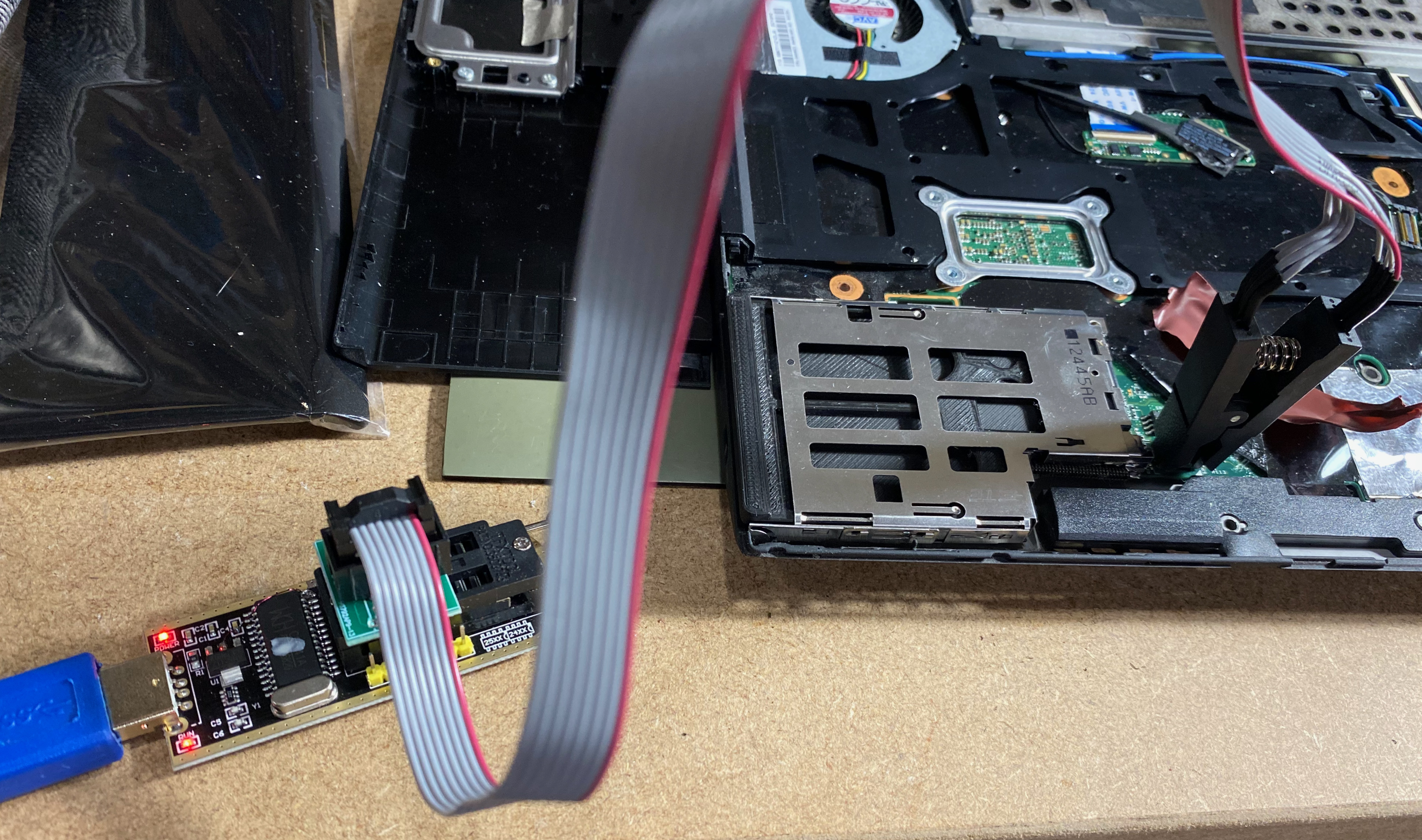
The CH341A I purchased comes with a SOIC clamp such that it’s possible to read/write the EEPROMs without de-soldering them. This relies on any other chips (such as the other EEPROM) leaving their I/O pins in a high-impedance state to prevent bus-conflicts when programming. Luckily, the protocol used is SPI which does this when the chip-select pin is de-asserted. As the programmer provides the SOIC VCC, it also relies on nothing power-hungry connected to the same rail.
To connect to the programmer, the cable must be connected to the right end of the ZIF connector with the correct orientation. To find the correct end, simply match the EEPROM-type against the key on the silkscreen. For the orientation, match pin 1 of the footprint (identified by a notch) to the red wire on the cable – the same for the EEPROM/X230 end.
I believe there’s a windows utility for the CH341A, but I didn’t use it. Instead I used the open-source flashrom utility on Ubuntu 20.04 which worked extremely well; instructions will follow.
After removing the keyboard and palm rest, the motherboard protective coating in the bottom right needs to be peeled back temporarily to reveal the 2 SOIC EEPROMS.
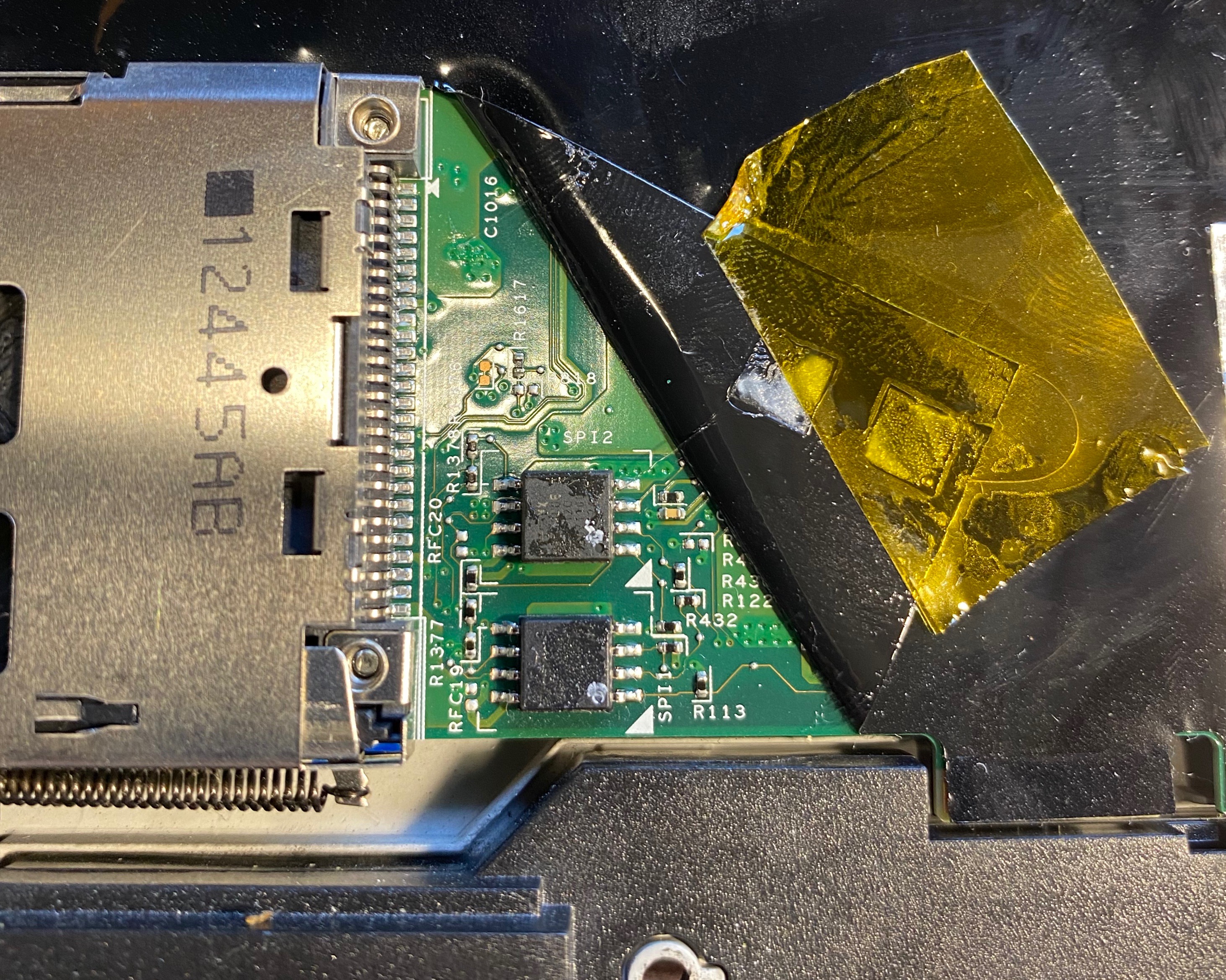
The top EEPROM is 4MB, the bottom 8MB. I believe the top contains the main BIOS, the bottom containing things like the Intel management engine and gigabit ethernet firmware.
For the purposes of this article ~/x230 is chosen as the work directory.
mkdir -p ~/x230/dump && cd ~/x230/dump
The top and bottom EEPROM can be dumped with the following two commands. Note that the EEPROM models used might vary with your board revision and position – you’ll need to tell flashrom which model
sudo flashrom -p ch341a_spi -r factory_top-1.bin -c "MX25L3206E/MX25L3208E"
sudo flashrom -p ch341a_spi -r factory_bottom-1.bin -c "EN25QH64"
Run both commands several times, incrementing the bin file number so that sha256sum can be used to check the dumps are consistent; this is important!
Next, the dumps should be combined into one image; after this the image can be handed to ifdtool to split into the constituent parts required by Coreboot.
cat factory_bottom-1.bin factory_top-1.bin > factory-combined.bin
factory-combined.bin will be used in the next section.
Configuring coreboot
Coreboot BIOS images are generally not available pre-built due to the required proprietary binary blobs extracted in the last section. To compile coreboot, it is possible to compile manually or by using a maintained script targeted for a specific platform such as skulls.
I decided to compile manually from coreboot.git as I needed to apply the FHD Variant patch which was not covered but Skulls at the time.
Coreboot recommends that regular consumers build from master, only OEMS and system integrators are advised to build from a released version. Nonetheless, I’ll provide the git commit I used to ensure things don’t change and make this guide less useful.
git clone https://review.coreboot.org/coreboot.git
cd coreboot
git checkout 81a2f45bd2e11ec0cfd699e583eb5e295725b110
git submodule update --init --checkout
The first thing to do is compile the toolchain for the target architecture; note that it’s possible to compile for all supported architectures with make crossgcc, but that takes far longer.
sudo apt install build-essential bison flex gnat nasm  # assuming ubuntu 20.04
make crossgcc-x64 crossgcc-i386 CPUS=4 # 25 minutes
After this, the necessary binary blobs (extracted earlier) need to be extracted using ifdtool and placed/renamed into the right location.
cp ~/x230/dumps/factory-combined.bin ~/x230/coreboot/util/ifdtool
cd ~/x230/coreboot/util/ifdtool/
make
./ifdtool -x factory-combined.bin
Rename the resulting files:
mv flashregion_0_flashdescriptor.bin descriptor.binmv flashregion_1_bios.bin bios.binmv flashregion_2_intel_me.bin me.binmv flashregion_3_gbe.bin gbe.bin
Copy them to the correct new directory:
mkdir -p ~/x230/coreboot/3rdparty/blobs/mainboard/lenovo/x230/
mv *.bin ~/x230/coreboot/3rdparty/blobs/mainboard/lenovo/x230/
Now it’s time to configure coreboot; coreboot config is stored in .config within the root of the repository. It’s a long-winded file so coreboot comes with a few configuration UIs for it – much like openwrt. make nconfig will launch a ncurses based UI to configure. Here are the options you’ll want to set, based on this guide:
- General setup
- Use CMOS configuration values
- Mainboard
- Set Lenovo X230 as model.
- 12MB ROM size, which is the default.
- 0x100000 CBFS (coreboot filesystem) size (also default)
- Chipset
- Include CPU microcode in CBFS (effectively CPU micro-firmware used to fix bugs etc. Windows/Linux will patch this anyway on-the-fly, but it’s best to do this as early as possible for security and stability reasons.)
- Add Intel descriptor.bin (
3rdparty/blobs/mainboard/$(MAINBOARDDIR)/descriptor.bin) - Add Intel ME/TXE firmware (
3rdparty/blobs/mainboard/$(MAINBOARDDIR)/me.bin) - Verify the integrity of the supplied ME/TXE firmware
- Strip down the Intel ME/TXE firmware (Important! This runs me_cleaner which disables the Intel
backdoorManagement engine) - Add gigabit ethernet firmware (extracted earlier, copied as-is) (
3rdparty/blobs/mainboard/$(MAINBOARDDIR)/gbe.bin)
- Devices
- Graphics initialization (Use libgfxinit)
- Display Framebuffer mode (Linear “high-resolution” framebuffer) Enable PCIe Clock Power Management Enable PCIe ASPM L1 SubState
- Add a Video Bios Table (VBT) binary to CBFS (src/mainboard/$(MAINBOARDDIR)/data.vbt)
- Generic Drivers
- PS/2 keyboard init
- Payload
- Add a payload (SeaBIOS)3
- (10) PS/2 keyboard controller initialization timeout (milliseconds)
- (Include generated option rom that implements legacy VGA BIOS compatibility
- Use LZMA compression for secondary payloads
- Secondary Payloads:
- Load coreinfo
- Load nvramcui
Finally, save and exit.
Full HD LVDS kill patch
The full HD patch needs to be applied. As the directory hierarchy has changed a bit since the patch, I chose to apply the patch manually after reading the change request description.
To apply it manually, the following files from the patch need to be replaced:
src/mainboard/lenovo/x230/Kconfig– tells coreboot the panel is connected to eDP instead of LVDS portsrc/mainboard/lenovo/x230/variants/x230/data.vbt– I think this is the video bios table.src/mainboard/lenovo/x230/variants/x230/gma-mainboard.ad– LVDS interface is removed from the port list.
Building & writing the new image
Time to build, in ~/x230/coreboot!
make
The resulting new BIOS image will be here: ~/x230/coreboot/build/coreboot.rom.
Next, the image needs to be split into a 4MB and 8MB pair:
cd ~/x230/coreboot/build/
dd if=coreboot.rom of=coreboot-bottom.rom bs=1M count=8
dd if=coreboot.rom of=coreboot-top.rom bs=1M skip=8
…and finally, the images can be flashed to the top and bottom EEPROMS. Connect to each and run:
sudo flashrom --chip "MX25L3206E/MX25L3208E" --programmer ch341a_spi --write coreboot-top.rom
sudo flashrom --chip "EN25QH64" --programmer ch341a_spi --write coreboot-bottom.rom
Now if everything went OK, you can connect the battery and boot up. Good luck!
Conclusion
I installed a 1080p IPS panel in my thinkpad, and it works great. No phantom LVDS panel any more. The X230 is a usable machine for portable hacking.
Future work
This is work that I am currently doing or will do – this blog post will be updated here when I can. I stopped here just to get this article out of the door…
Reduced standby power (NOT DONE)
I’ve read that the Nitrocaster board mod uses an always-on 3.3v rail, meaning the board and possibly screen is always drawing power. I have noticed that my battery will drain rather quickly even if the laptop is powered down. A post on daduke.org explains this and offers a coreboot patch that allows control of the power rail. I will do this mod and update here as soon as I have a method of measuring power consumption.
Windows 10 (DONE)
SeaBIOS cannot boot Windows 10, at least when I tried. I’ve heard it’s due to incomplete ACPI tables and/or Windows 10 requiring a uEFI past a certain revision – I’m not sure so consider this just a rumour. A fix may be to load the TianioCore payload (a uEFI) instead of SeaBIOS.
Edit: I swapped the SeaBIOS payload for the Tianocore payload. It was necessary to change the CBFS size to 2MB (0x2000000) instead of 1MB.
Working boot splash image (DONE)
Apparently, it’s possible to embed a cool-looking BIOS splash image into the ROM image – if the option is enabled, if a bootsplash.jpg is included in the coreboot filesystem (CBFS) then it will be displayed; with a few caveats. One is that the image has to be a VESA resolution, which means some stretching will happen so the image has to be inverse-scaled to match the aspect ratio of the 16:9 panel correctly. Another is that the JPEG decoder in coreboot is quite basic – the image must be encoded in a specific way.
My attempts yielded a splash image, but with the wrong colours and surrounded by noise – I’m not sure if this is due to the eDP Nitrocaster mod or faulty configuration.
EDIT: I got the bootsplash working after installing Tianocore. To do this I simply replaced the default coreboot hare logo residing in payloads/external/tianocore/tianocore/CorebootPayloadPkg/Logo/Logo.bmp. Note that:
- This won’t exist until after your first build, as tianocore is added as a submodule.
- Replacing it and rebuilding coreboot won’t work unless you remove
/payloads/external/tianocore/tianocore/Build/UEFIPAYLOAD.fd, so that tianocore is rebuild with coreboot - The GIMP won’t save the image in the correct format upon saving the image. You need to use
imagemagickto convert it toBMP3format. - There is a Tianocore configuration option to specify your own logo. I didn’t have time to figure this out especially combined with the coreboot build process.
Thanks for reading! If you have comments or like this article, please post or upvote it on Hacker news, Twitter, Hackaday, Lobste.rs, Reddit and/or LinkedIn.
Please email me with any corrections or feedback.