Design/build of some curved, fully parametric speaker cabinets
This post documents a saga of speaker design dating back to 2019. Since then, I’ve been gradually working on a CAD model for a new set of what started as (yet another) subwoofer, but became some compact 2-way office ribbon speakers.
The idea was to create a fully parametric design that could be easily adapted to any drivers, enclosure volume etc – yet still retain the original aesthetic.
OpenSCAD is my CAD package of choice – it’s a code-CAD system so I’m right at home. There are, however limitations which make certain things excessively hard or long-winded; even impossible!
With this project, I wanted to push the boundaries of what is possible with OpenSCAD and what I could make in my garage. I wanted these speakers to look like they could have been bought from a high-end audio store.
Design
I didn’t want a simple box like most speakers. Moving toward more higher-end speakers, more exotic shapes are used – often with compound curves and automotive grade finishes.
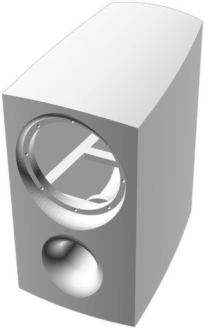
For a while the design was for a custom modelled bass-reflex subwoofer, but I decided to make some 2-way speakers after taking a look at Paul Carmody’s Speedster design; I was more excited about the idea of building a pair of full-range speakers considering I had already build a sizeable subwoofer. So, I decided to build some Speedsters instead.
Inspiration
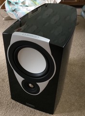
For about 6 years I had some Mission SX2 speakers. They were finished in piano black and were curvy – I wondered how the complicated-looking shape was made.
As it turns out, each curve was just a circular arc – the complexity came from the intersection of these arcs at the edges – elegant!
I also had some old Sony speakers with a flat conical profile at the front. I figured this would work well with the speedster design, considering the tweeter is inset somewhat.
I decided I’d like to lean into the compound curve idea a bit more – elongate the design, move the center of the main curve forward, and pitch the top up towards the back for a kind of forced perspective.
CAD approach
I mocked up the shape by intersecting 5 cylinders – one for each panel except the bottom. Moving around, I deviated from the SX2 design by moving the center of the side curves to the front, and angling the top for a slight incline.
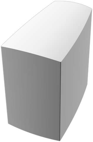
After some time I realised I could optimise the design quite a bit by intersecting 4 circles instead, and then extruding to intersect with a single cylinder. This, and setting the number of faces ($fn) throughout the design reduced the eventual build time to 3 minutes instead of around an hour.
The extrusion approach also allowed me to use offset() to round the sharp edges of some of the panels. As it’s OpenSCAD, I couldn’t round the other edges – these would have to be rounded later by sanding as a post-process.

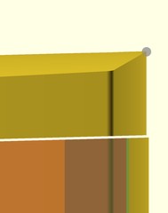
In the above image, you can see the derivation of the curve of the left panel – using an offset, large circle.
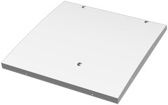
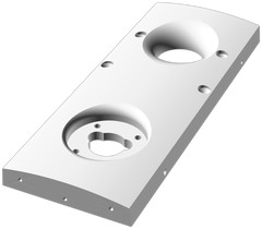
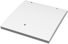
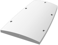
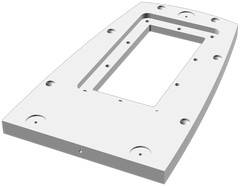
Given I intended to subtractively mill the design from 18mm MDF or birch ply, I had to convert the shape into a series of panels with no overhangs. The approach I used was simple – to intersect an “infinite” panel with the edges of the basic shape, and subtract the adjacent panels from each.
This approach is illustrated above. From the combination intersection, you can see how 2 possible side and rear panel sizes could be derived – the rear could be wider and extend to the sides, or the side panels could be longer and extend to the rear.
The side panel intersections were the most tricky as they had to be at an angle and offset determined by the centre of the circle defining the curve as well as the depth. This was necessary to ensure the panel was of even thickness on both sides.
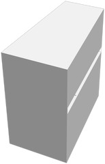
Given the design was not a simple box, I needed a way of arriving at the same internal volume as the box design. I used a similar method to calculate the shape of the internal volume, and then used admesh to measure the volume of the shape. It was then a simple matter of iterating on the depth until the volume matched the box design. Note that I kept the front panel the same size – this is important for the acoustic design as the baffle step affects the frequency response.
I wonder if my design (vs a box) is acoustically superior in one way: thanks to the curved design, there are no parallel surfaces – this could reduce standing waves and resonances.
Beyond this, a disclaimer – I know I’m modifying the original design which is something Mr. Carmody warns against. I think I’m being sensible though!
Driver holes
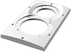
I made a generalised negative cut-out to support any circular driver. The design accepts the panel thickness, driver inset, bezel thickness etc. It also supports either a conical or rounded flare for when the driver is inset.

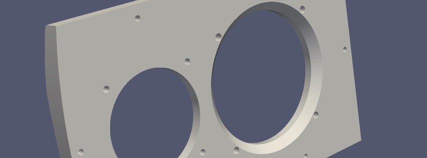
On the reverse of the front panel, a chamfer is added to reduce turbulence behind the driver. See this article for more information – it’s important!
Screw holes
I thought a long time about how I would construct the design. Most importantly, how would I align and clamp the panels for gluing?
I considered using dowels, brad nails, clamps and jigs. I remembered my horn-loaded subwoofer and how I used screws to align and clamp the panels as recommended in the design; it worked excellently! If I could manufacture pre-determined holes with a calibrated profile, I could use regular cabinet screws to allow fast assembly with no clamps at all.
One downside is that I would have fill the resulting holes; a good compromise in my opinion. Another is that depending on how I manufacture the panels, it may be difficult to get accurate holes.
Most of the design was implicit, meaning I didn’t actually know the specific co-ordinates of a lot of the features such as most of the geometry of the rear panel. This was fine, except for placing screw holes.
For a long time the design had some “guesses” with hard-coded offsets to determine he position of the screw holes. This is because there’s no way of addressing a corner, edge or surface in openscad – it’s CSG only and not a BREP system.
This meant that for a truly parametric and fully qualified design, I’d have to derive the locations manually. I won’t go into detail but it was basic trigonometry, just a lot of it.
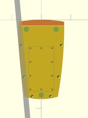
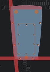
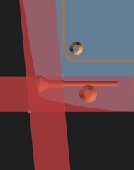
I used some simple techniques to align the screw holes – placing debugging cylinders at the calculated positions to check they were correct, using the orthogonal view aligned to a plane to validate the positions.
Crossover
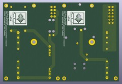
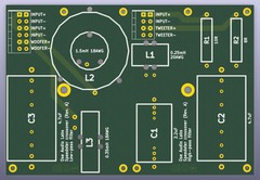
The crossover in the speedster design is a fairly complex (and therefore bulky and inefficient) third-order design. This would make it a pain to manually construct in a reproducible manner, so I wanted to create a PCB for this purpose.
Luckily, Greg Ose had kindly designed one on github. It was fairly large as it was designed to accommodate variety of possible inductor/capacitor/resistor sizes – not a problem on a rectangular speedster design but a little challenging to fit inside my design.
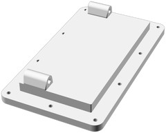
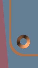
In the end I designed an access panel at the bottom of the speaker to allow easy installation of the crossover. This was a lot of effort but worth it – what if I had sealed in the crossover and it developed a fault?
| |
The above is the algorithm set to calculate the right number of screws to achieve a minimum space between each, and then fit them evenly.
The design held the crossover together with 20mm standoffs, attached to the access panel in a vertical orientation.
Gaskets
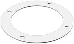
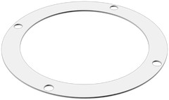
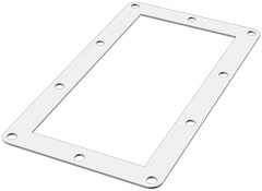
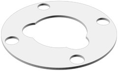
To properly seal the speaker drivers, rear connectors and access panel, I had to find some kind of gasket material. It’s possible to buy foam tape, but that seemed quite messy.
I thought the best way would be to manufacture the gaskets to be the perfect shape, complete with bolt holes. I first experimented with a 3D printed design using TPU filament, but the resulting gaskets felt too hard and I didn’t think it would seal well.
In the end I found some 1mm self-adhesive EVA foam. If I could get some time with a laser cutter I could make them easily and get a great seal!
Nesting & post processing
I like the idea of a fully automated build chain; in addition to being full parametric, my design produces renders of all the parts, optimised STLs and even places the parts on individual beds/plates.
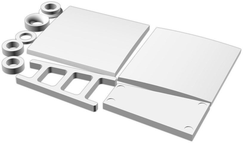
This was more necessary when I was targeting CAMBAM or PyCAM, which are quite basic so don’t include the ability to automatically place parts. Iterating the design would involve a lot of manual placement and check steps if I didn’t automate this process!
I combined rectpack with numpy-stl to produce a script that not only nests parts, but also places the parts on the minimum number of beds. Given the opportunity, it also bounds checks the result and places the parts down flat to ensure it is manufacturable on a given machine.
Parametric design
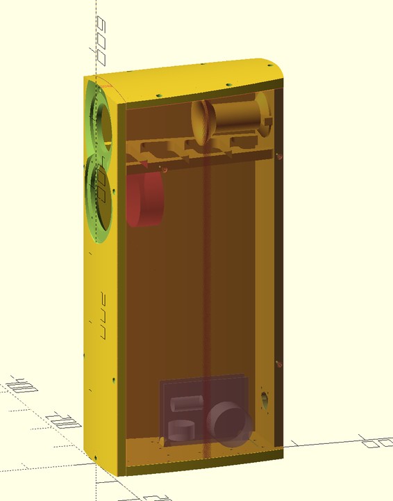
As the design was fully parametric, I could change a single variable to move to a floorstanding design. Of course the acoustic design would have to change, but this makes it easy to experiment with different designs create variants with far less effort.
All of the panels and screw positions are recalculated to fit the new dimensions. I would probably have to break up the design into sections and add more braces to make a floorstander feasible though.
Final renders
As detailed in my OpenSCAD article, the Makefile for the project produces some crisp looking renders.
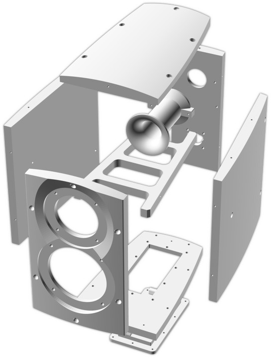
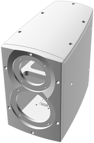
The above shows how the panels are assembled. Below, all panels.
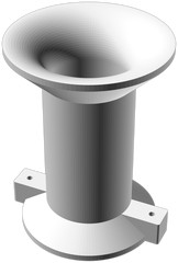
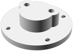

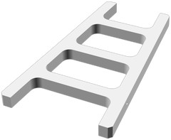
Manufacturing
I had designed the speaker to be manufactured using a CNC router. I had access to one via a friend – we spent a whole year of Wednesday evenings getting it to work, ultimately to conclude that the Mach3 based controller was a dead-end – too unreliable. We had plans on building a new machine, but that plan got put on hold due to work commitments from us both.
One day I had a realisation – the speaker could probably be printed using my X1 Carbon as the build plate was nearly as big as the speaker was tall; perhaps I could divide up a panel or something…
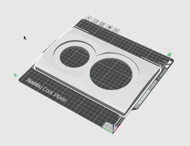
As it turns out, I could, without even dividing any panels. I did this by making the speaker wider, shallower and shorter; as well as changing the bottom panel to take up some height from the side panels. Literally millimeters made the difference!
Given this marginal fit, the nesting system I developed was less useful, especially considering bambu slicer can do it better natively. The script was still useful for bounds checks and to give an initial go at layout.
3D printing
PLA was my natural choice. It’s the easiest to print with, and given the speakers won’t be left in the sun outside I think the relatively low temperature tolerance won’t be an issue.
The density of MDF is around 500kg/m^3 versus PLA at around 1240kg/m^3. So this means I could print at 50% infill and exceed the density of MDF.
First I tried 90% infill. It did not go well. There was terrible curling with the default settings with the X1 carbon; unacceptable! I reduced to infill to 50% which helped – less plastic, less shrinkage in theory.
I attempted to improve bed adhesion by cleaning the plate with isopropyl alcohol and spraying it with hairspray. This helped, but the part ended up pulling the bed up with it…
I took a look at the settings. As it turns out, the plate is called a “cool plate” for a reason! The default settings leave it at 35c, which is far less than the 60c I used to use with my old printer (a janky Anet A8).
Whacking up the temperature fixed the problem entirely – only after wasting about 3 spools messing around. Luckily I got a deal on some cheap PLA – £10 a reel from “TECHBEARS” – a company I’ve never heard of. Not issues though, beyond the original curling.
Before I knew it I had printed all 18 parts. It took about a week of constant printing. Having the AMS unit really helped, as it automatically moved to the next spool.
Brass inserts
Heat-set brass inserts that have knurled edges are commonly available. They are generally pushed in with a soldering iron, and secure themselves in the plastic as they cool. They are an alternative to making a thread, using loose nuts or standoffs.
Generally the inserts have a shank and a protruding lip at the top an bottom. I experimented quite a bit with the size of the hole; what I found was:
- If you get it to small, the plastic builds up and the insert wanders
- If you get it too big, the insert doesn’t grip as well and can fall out
- Use a pair of tweezers to steer the insert so it ends up straight
- Be ready to hold the insert with the tweezers in case the soldering iron catches
A balance between the two is necessary. I found about halfway between the two diameters was optimal. Any squeeze-out can be removed with a narrow drill bit and hammer.
A test fit showed that everything fit well, which was a relief as I didn’t allow any margin in most cases. Some bolts were a bit tight on the access panel, that’s it.
Gluing & assembly
I decided to use epoxy glue to assemble the parts – cyanocrylate would have worked, but may not have sealed the edges as well. It is important to make sure there are no air leaks which would compromise the acoustic performance.
I keyed in the surfaces using some 40 grit sandpaper to aid adhesion – little effort was required. I cleaned the surfaces with isopropyl alcohol – important to remove any oils and more importantly hairspray residue from the 3D printing process.
The screws were perfect for aligning and clamping the panels, removing process variance. I used plasterboard screws as they’re cheap and I have thousands of them. I designed a calibration part to prevent any movement, and to ensure no expansion of the substrate plastic with appropriate tightness. The calibration part also served as a mechanism to measure the compressed foam depth with several layers divided for increased accuracy.
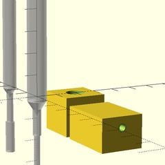
Assembling the panels in the following order made sure every part was fully constrained and easy to align:
- Bottom panel
- Rear panel
- Brace
- Bass reflex tube
- Left side panel
- Right side panel
- Top panel
- Front panel
Surprisingly, I used only one 25ml “Gorilla glue” Epoxy syringe – there was exactly the right amount for both speakers! I had no idea how much I’d need.
Surface preparation
It was important to me to make sure the final result didn’t look 3D printed. As such, I needed a smooth finish without showing any joins or layer lines.
To achieve this I used my random orbital sander with 60, then 120 grit – making sure to use low speed as the PLA can melt easily and burrs will form everywhere. I also made sure to avoid over-rounding the edges and particularly corners – one slip and they’re done for!
I rounded the sharp edges that I couldn’t round in the design with 120 grit sandpaper by hand. I also did the bass port by hand, which was a pain until I found a tube to wrap the sandpaper around.
After this I used “Big boy” 2-part fine surface filler after a quick wipe with isopropyl alcohol. I reckon about a 3 golf ball sized blobs are sufficient per speaker – it cures quickly so don’t use too much at once, and limit the activator. I reckon 15mm of activator was enough per golf ball sized blob.
The consistency was that of margarine at first, but within minutes it became like hard-to-push plasticine. I used the included plastic scraper to push it around and fill the screw holes.
Given it cured so quickly, the above was the result. A bit of a mess, but it didn’t matter – it just meant more sanding.
After sanding with 240 grit, the result was starting to feel smooth – no layer lines to be felt at all. I did, however, notice some of the screw holes had pitting so I had to iterate a few times. It was only some time after that I realised the pitting was probably caused by sanding dust getting into the filler – I should have cleaned the surface first with air or water!
Next I gave the cabinets another clean with isopropyl alcohol to remove any grease before taking them to the spray tent (which was really a beach tent) and masking the brass inserts.
Painting
I put some long woodscrews in the feet holes to act as a stand. This worked well, and allowed me to spray each cabinet in one go by holding the cabinets by the braces. I sprayed on a few layers of adhesion promoter and left them overnight in the kitchen where it was warm.
After this I sprayed the cabinets with 3 coats of black primer. In retrospect, I should have used plastic primer but it seemed to work well. I followed the primer with some Hicote bed liner – a thick, textured paint that is supposed to be durable.
A word of warning – the bed liner gets everywhere! I left the parts to cure overnight in the kitchen.
After curing the speakers looked fantastic – you couldn’t see the panel joins at all! A little texture and a few screw holes were visible though; I could have taken more time to deal with them but I have finite patience…
Gaskets
I ended up getting a great deal on a Creality Falcon 10W CR-Laser cutter in the end, after asking around to see who had access to a cutter.
With lightburn, I was able to cut the gaskets out of 1mm EVA foam straight away after minimal experimentation. It’s a great bit of kit – 10W is a lot of power for foam. I reckon the 5W one would have worked just as well (albeit slower).
I was able to run at 10,000mm/min at 80% power in a single pass. That meant cutting time was reduced too well under a minute.
Final assembly
The gaskets fitted well, despite being a little fiddly. The speaker drivers were fine, though the bolts were tight due to the brass inserts being slightly off.
I was happy to see that my experiment with the foam thickness resulted in the drivers fitting correctly.1
When fitting the crossover I found the speaker wire I had didn’t take to solder well at all. Substituting for some mains flex, I had no problems.
Before closing I put a “couple of handfuls” of polyester stuffing inside, making sure to get all empty space. This increases the apparent volume of the speaker. https://pypi.org/project/numpy-stl/
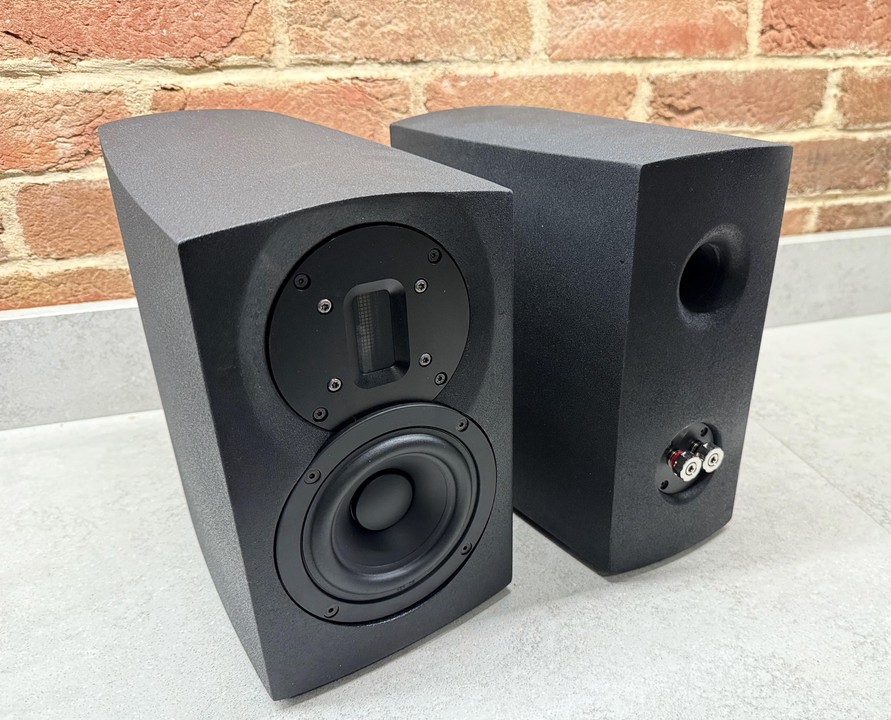
I measured directly instead of trusting the driver datasheets ↩︎
Validation
I measured the response at near field (using room EQ wizard) to make sure the polarity of the drivers (with respect to each other and left/right) are correct – else I could unknowingly end up with a notch in the crossover frequency – or worse, cancel bass between the speakers. I have a calibrated measurement mic for this.2
I have read that the Foundtek ribbon driver can have reversed polarity sometimes in forums. It’s also possible that the crossover design or my wiring could have a mistake.
According to the original speedster design, the crossover should be around the 3000Hz region. We should not see a dip at this frequency – if we do, it’s likely the drivers are out of phase. They should be pushing and pulling at the same time around this crossover point.
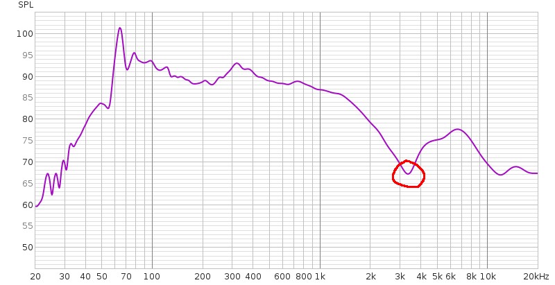
The above shows a dip at 3.5kHz – the drivers could be out of phase. I swapped the polarity of one of the tweeters to see what it did to the response.
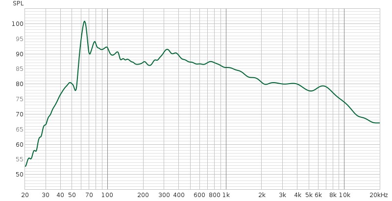
As it turns out, swapping the polarity of the tweeter fixed the dip! The response above is much smoother. I’m glad I checked it!
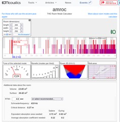
A friend pointed out the peak at around 70Hz and suggested it could be a room mode. Plugging the numbers into this generator seemed to confirm it! I shall use Room EQ Wizard and something like CamillaDSP should I feel the need to correct it. Not sure I can justify another MiniDSP.
Note that I was using my Sony amplifier and could not turn off the DBFB feature, so the plot is influenced by not only the room, noisy children, but also this feature.
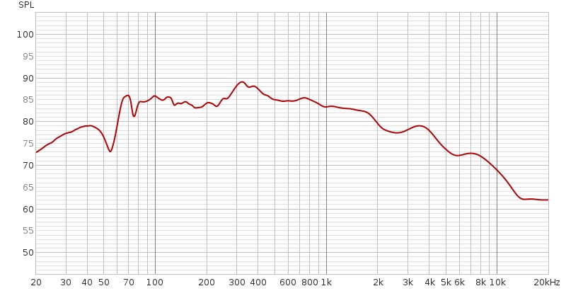
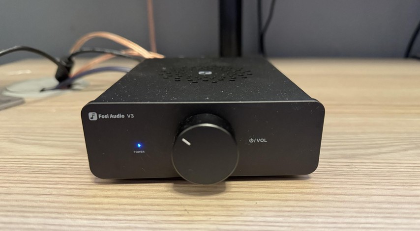
Later on I tried the Fosi amplifier. The large 70Hz peak was gone! This means the room mode theory was a distraction; the cause was the DBFB feature of the Sony amplifier.
A few comments on reddit suggest the high frequency looks bad. I agree that the measurement method wasn’t right – I am likely getting a bad reading due to acute roll-off in that position due to the dispersion of the tweeter.
I will have to measure at a greater distance to get a more accurate reading.
As for the polarity between the speakers, I generated a 60Hz tone and checked that the SPL increased when driving both speakers at once. Much like when setting the phase of a subwoofer, the SPL in the listening position should increase when the speakers are in phase. It did!
UMIK-1 – and several others for some reason. ↩︎
Conclusion
Fit & finish
I was surprised at how neat the speakers looked. They didn’t look “DIY” which was one of my aims.
If I were to make them again, I’d make sure the screw holes were properly filled, and use more filler elsewhere as it’s possible to see the 3D printed texture and screw holes in some places with the right light.
I’d also make sure the bass port has enough paint – it’s a bit thin in places, but I don’t mind for now as it’s not visible during use where I’ve got it set up.
Bed liner paint was a good choice – I like the even finish. Perhaps I could experiment with sanding the finish and possibly waxing it or something on a test piece.
Construction & design method
I’m pleased to say the design method of creating a shape and intersecting panels, combined with clamping screws worked extremely well. There were no issues (in the end) with panel warping or accumulating errors.
I was a little worried about accumulating errors, but thanks to the accuracy of the screw clamping method, decent 3D printer and viscous glue, there were no issues.
Given it’s parametric I dare say I’ll make some other speakers in the future with the same design. Possibly the Virage now that I have the Paul Carmody bug.
How do they sound?
TL;DR: Great! Best speakers I’ve heard, possibly ever.
First I hooked them up to my office amplifier, a 25 year old Sony. Unfortunately even at max volume they were not loud enough. The amp was clearly struggling – playing a sine wave would result in audible clipping.
Why was it struggling? It has no problem driving the 6 ohm speakers it came with. The answer lies in the crossover – it’s a third order design and therefore inefficient compared to a simple first-order crossover. These speakers need power!
Despite this, vocals sounded amazing and there was a surprising amount of bass – as is characteristic of the speedster design.
The speakers were rather boomy in my office. I suspect this is due to the DBFB feature of the amp – bass enhancement tuned to the sony speakers it came with. Given this and the power problem, I reserved judgement until I got a proper amplifier.
So what amplifier would make sense? Requirements:
- Small form factor, it’s on my desk
- Enough power to drive the speakers
- Good sound quality – no distortion
- Reasonable price
I consulted Audio Science Review to find a suitable amplifier. The reviews here are objective and based on scientific assessment by Amid.3 I settled on a Fosi V3 and got a good deal.
After this they sound far better. No longer boomy, and a great sound-stage. “Holographic” is the meaningless audiophile word I’d use.
SINAD, SNR, FFT, THD, IMD, etc. ↩︎
Similar designs
Interestingly, I discovered that I’m not the first to complete a curved design – fouchagalaga has made a 2-curved speedster design which looks great.
What’s next?
I could design a larger set of speakers next – possibly a floorstanding design. Maybe also, I could use this design base for a SFF PC case!
If I get the chance, I’d love to compare my speedsters with a set made from wood. While the density is approximately the same as MDF, the damping qualities of PLA may not be as good. This could be mitigated by the lack of parallel surfaces, however.
Also I’ve been told by no less than 5 people,4 given we’ve converted the garage into a fitness studio for my wife’s PT business, I have to build a new workshop in the garden for future projects…
Instigated mainly by Oliver, who owns the DIY CNC router. I say, Oliver, I will, as soon as you build your new CNC machine! ↩︎
Acknowledgements
Thanks to Paul Carmody for the original speedster design, Greg Ose for the crossover PCBs.
Updates
I didn’t quite like the wedge stands I made, shown earlier. They were too chunky; I iterated on them a bit before abandoning them altogether.
In the end I settled on some minimalist legs that reflect the design language of the rest of the speaker. Much better!
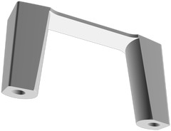
…you may have noticed the dust however. The bed liner finish is incredibly rough, so much so that it just sticks to whatever dusting cloth you try to use. I guess I’ll have to re-finish them a bit later, perhaps sand them down a bit.
Thanks for reading! If you enjoyed this article or have comments, please consider sharing it on Hacker news, Twitter, Hackaday, Lobste.rs, Reddit and/or LinkedIn.
You can email me with any corrections or feedback.
Tags:
Related:
