
Rackmounting that which should not be rackmounted
A few years ago I developed a few clever ways of rackmounting non-rackmount equipment so it could look neat in my HiFi rack enclosure.1 The goal was to have a professional-looking setup that would support input from my TV, spotify, Airplay, DJ controller and other sources while being able to drive a subwoofer with room correction and integrated crossover.
As part of this I also developed some HiFiBerry accessory hardware and code to allow streaming, input selection, remote volume control and track identification.2
The rack conversions, hardware and code weren’t used long (as I tend to change around my HiFi gear frequently) but I figured given the work I put in it’s likely useful to someone else wanting to rackmount their HiFi gear or mess with HiFiBerry hardware.
I enjoy the idea of modular systems, especially when it comes to HiFi. The ability to swap out any part to upgrade incrementally is appealing, as well as the possibility of producing custom enclosures and panels to integrate everything together.
What follows is a (somewhat disjointed) cronicle of my journey to build a professional looking custom 2U rack unit to combine a DAC, input selector, streaming device and power routing for my HiFi system.
If you’re interested in doing anything similar, you may benefit from reading about the problems and solutions I’ve encountered along the way.
First prototypes
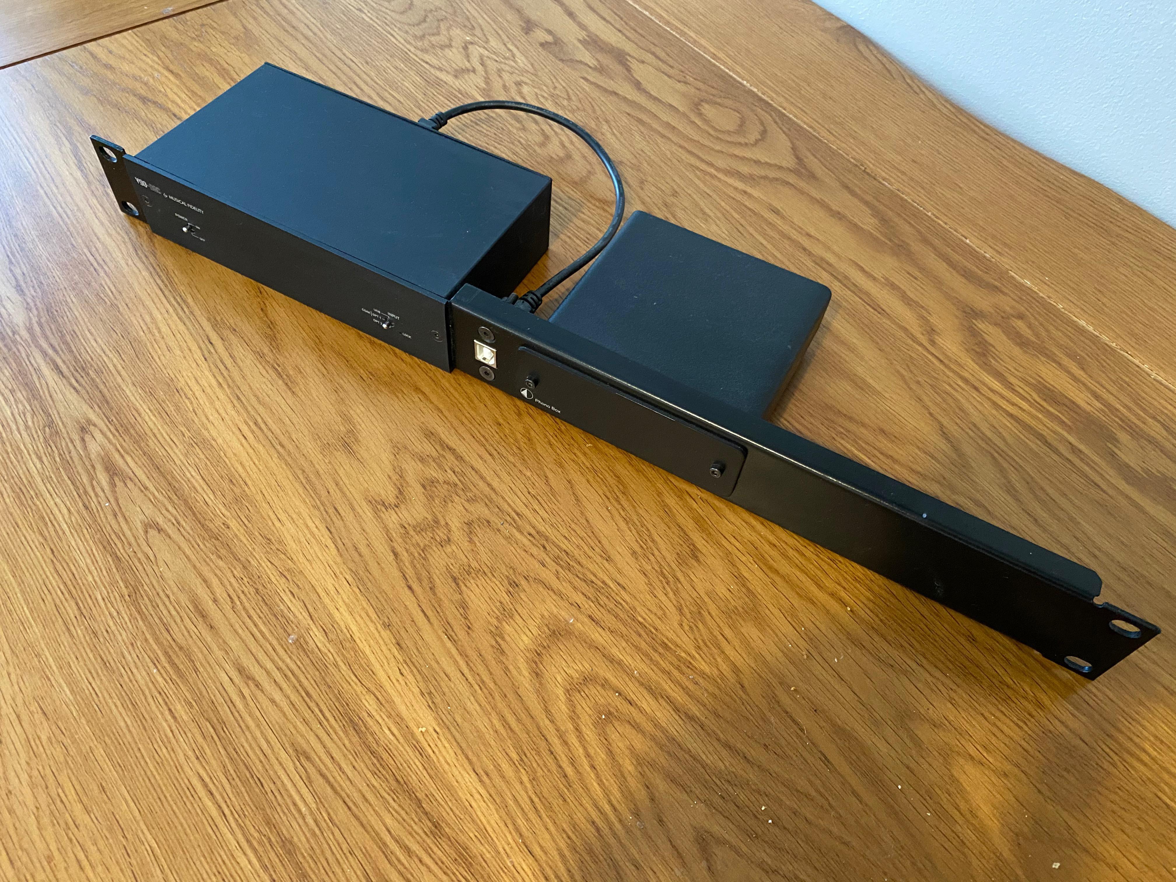
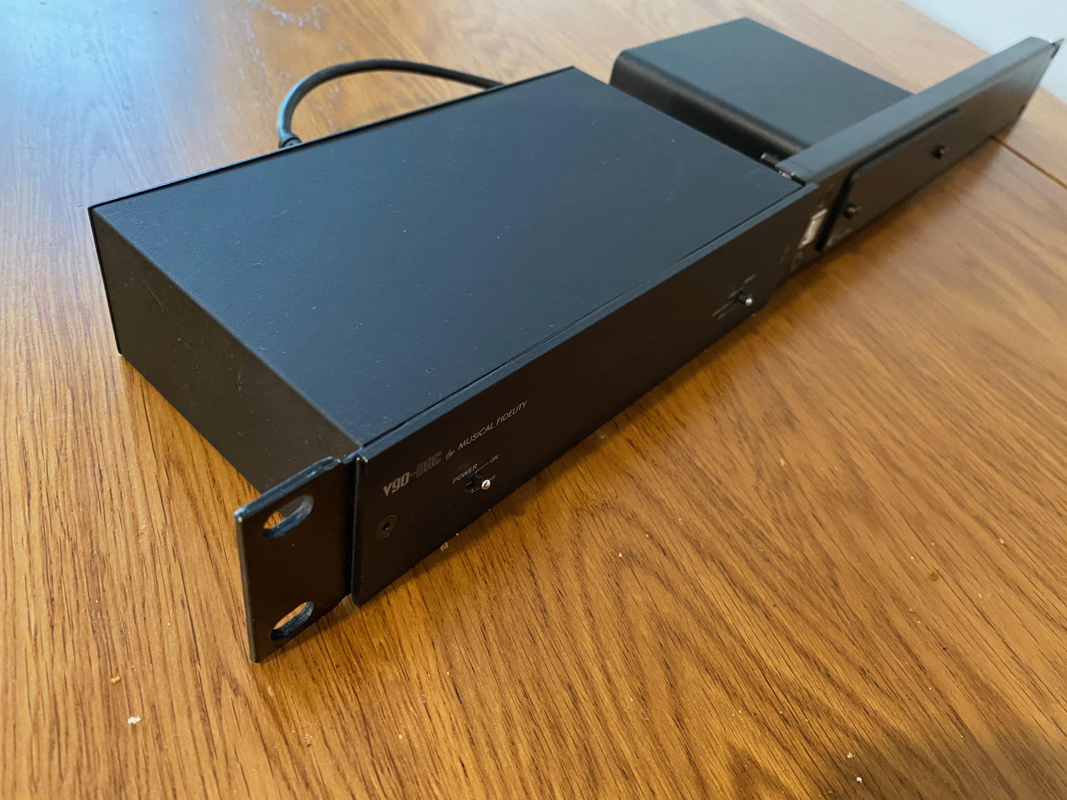
Before this upgrade I converted a DAC (with USB beside) and phono pre-amp. I had a 1U blank plate where I drilled holes to allow it to sit behind the face plate of short equipment. This worked really well – I installed a DAC and a phono pre-amp, complete with front USB connection. Of course, this only works for items with detachable face plates so it limited what I could buy.
The plan was to create an input selector with a pre-built 1U enclosure. It would contain a relay board, microcontroller and motorised 4-channel volume control to allow automatic selection of source while remembering the volume.
I actually got quite far along with the selector project,3 but lost interest when I realised I could achieve the same thing after finding a Cambridge Audio DACMagic without spending more time.
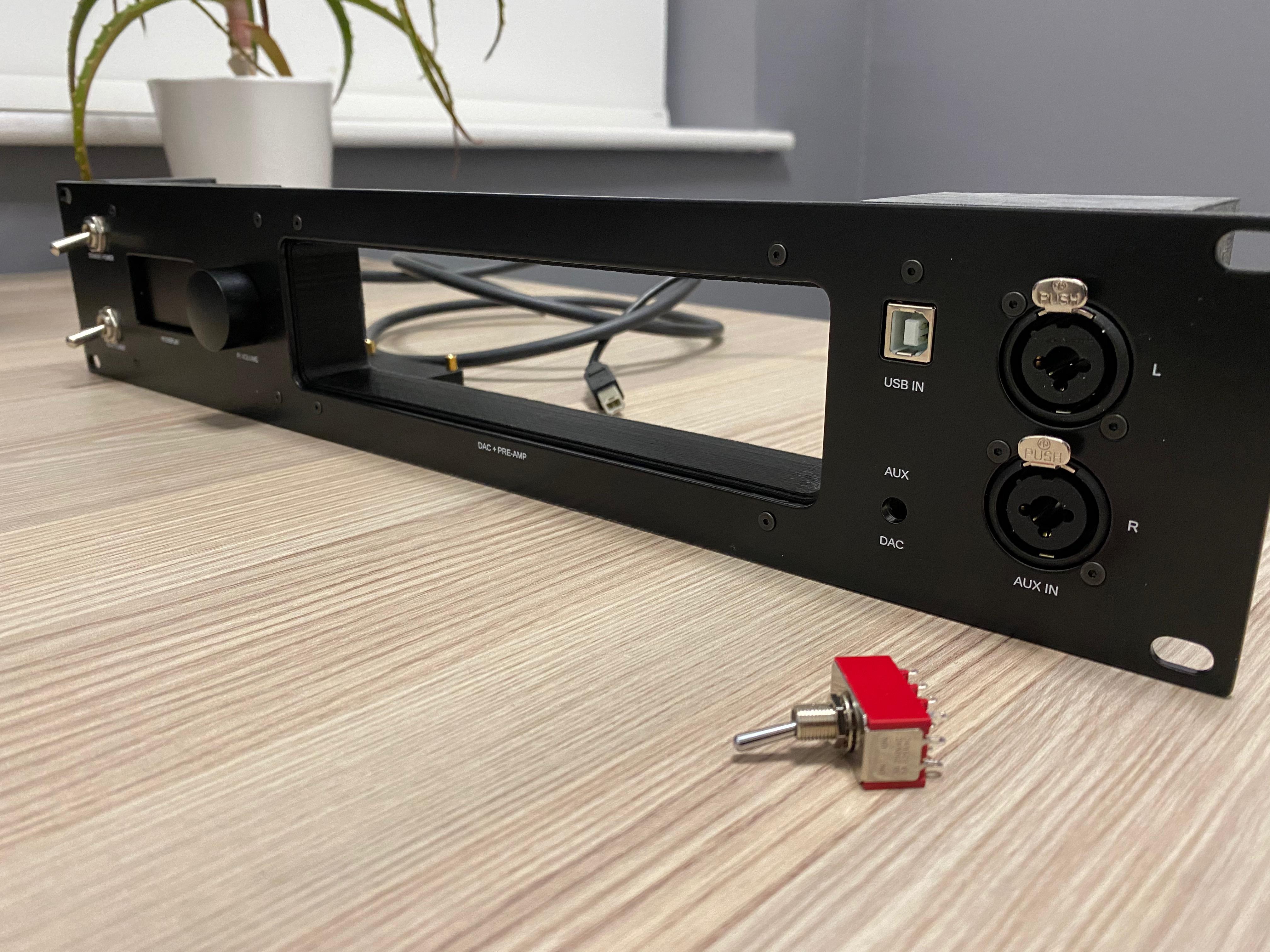
The DACMagic had a volume control, input selector and balanced outputs. This was taller than 1U so I’d have to use a 2U panel if I wanted to do the same as above.
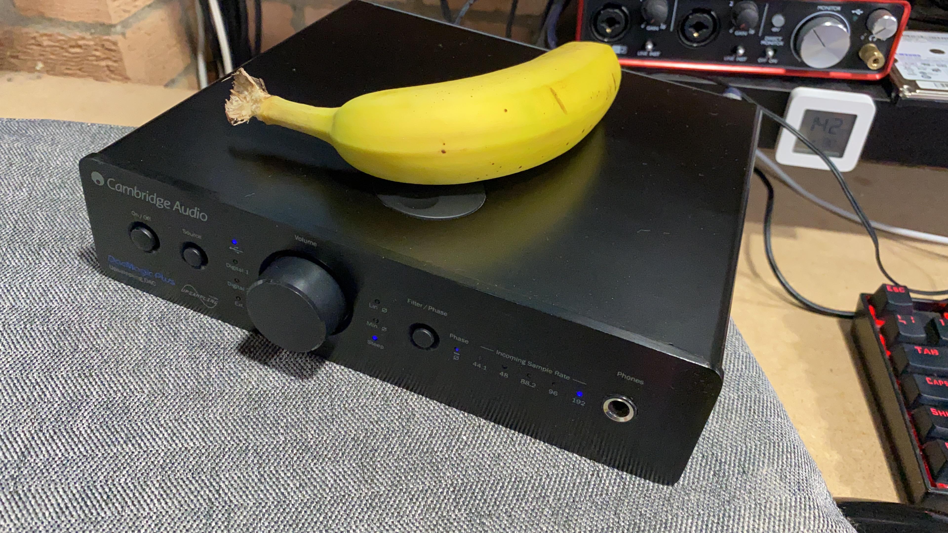
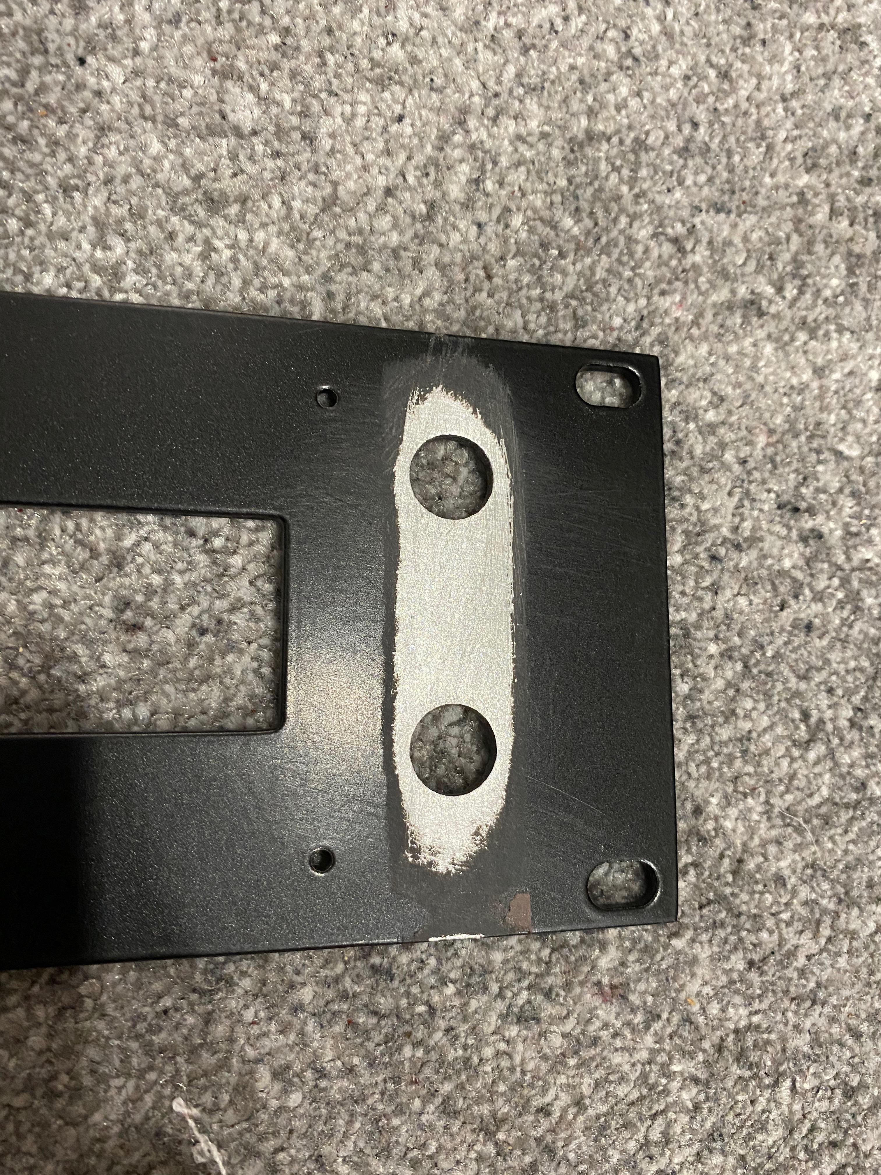
The front panel of the new DAC was also much more complicated so the old interposing method wouldn’t have worked well; I needed to cut out a large hole surrounding the face plate this time – which meant hand-cutting it like last time was not viable.
It even had a motorised volume control with custom position sensor and a small OLED display! ↩︎
Modelling in CAD
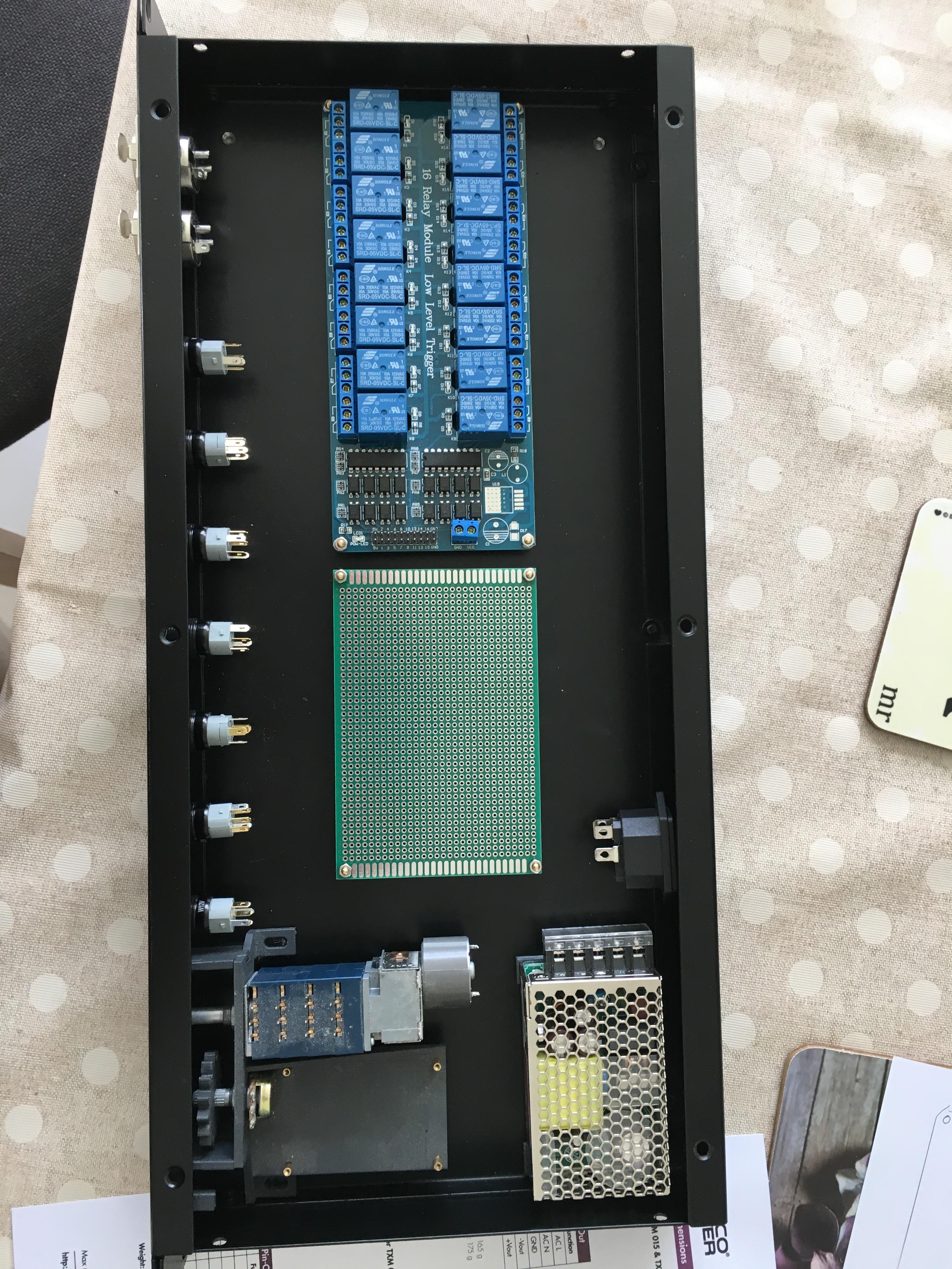
I chose to make the main panel out of 3mm aluminium, with 3D printed junction boxes and brackets. With OpenSCAD I used a hierarchical file layout to enable the parts to be easily separated and rendered for manufacturing while allowing an assembly view for sizing and easy layout.
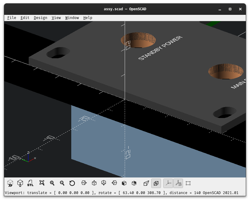
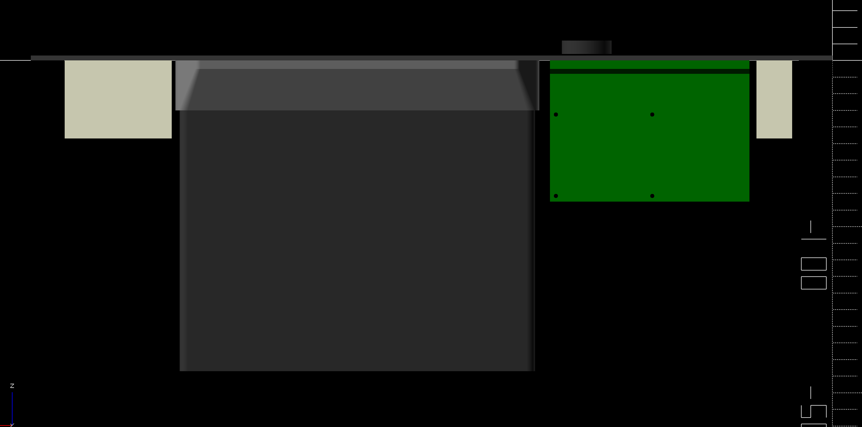
My approach was to use a co-ordinate system as above, where the origin is the on the left of the plate, half way up, at the bottom. This made most of the transformations easier and provided a half-height reference for alignment.
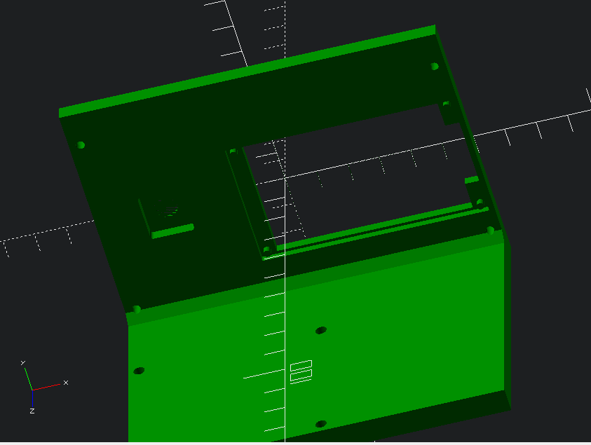
I then designed several boxes to hold the various components; the boxes were attached either with brass heat-set inserts, or took advantage of the connector mounting holes.
The DAC bracket was designed to hold the unit floating as a cantelever in mid-air. I used a rebate to keep it flush with the front of the panel and prevent it going back into the case. The bracket was around 30mm deep, which was later determined to be enough support despite the cables hanging off the back – it’s super lightweight, practically empty. Blu-tack prevents it from sliding forward!
As for the display and Pi, I designed a bracket to hold them together. The bracket accepted the negative of the display profile with some plastic stakes built into the design – they extended just past the holes in the display to allow me to melt them into place with a quick peck from a soldering iron.
The display was aligned with the appropriate hole in the panel over the active area of the screen only.
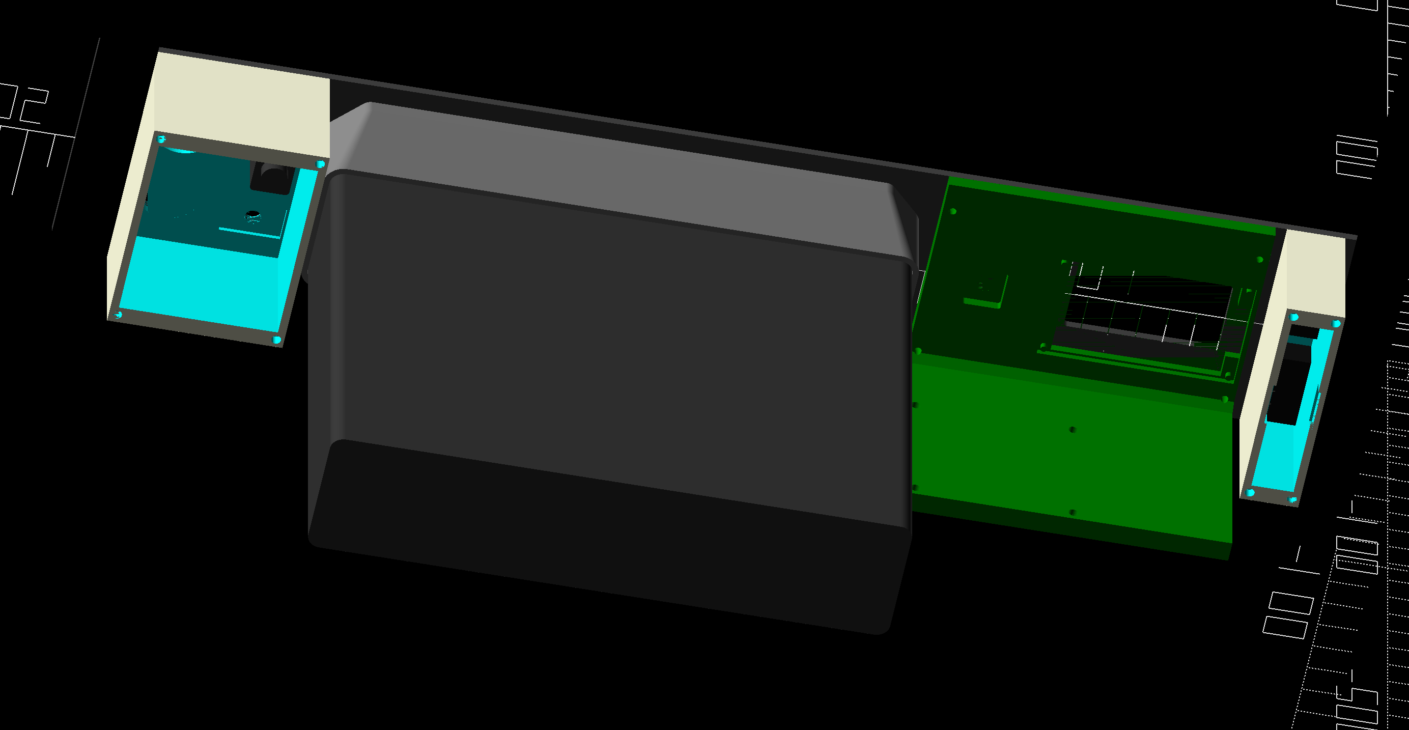
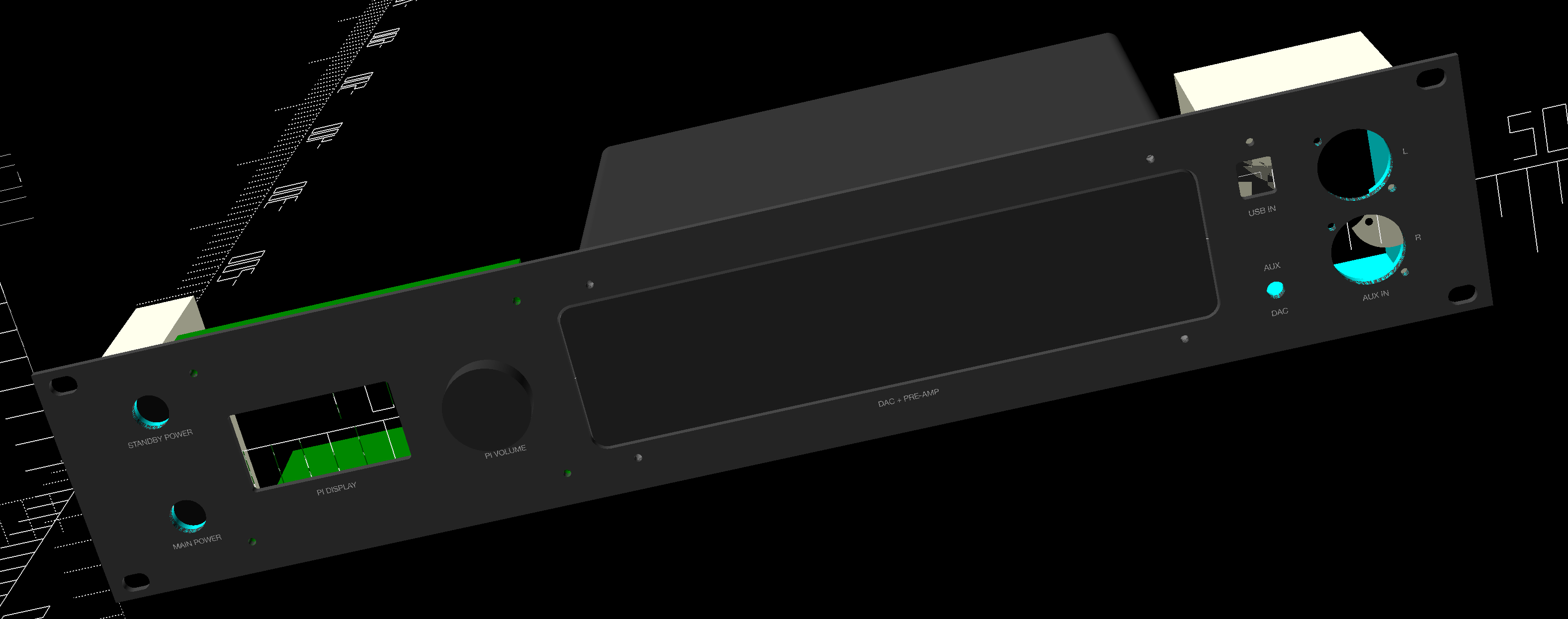
Given the hierarchical file layout, I could easily render the individual parts as well as the assembled whole. This allowed checking that everything would fit before manufacture; important as producing the metal face plate was expensive.
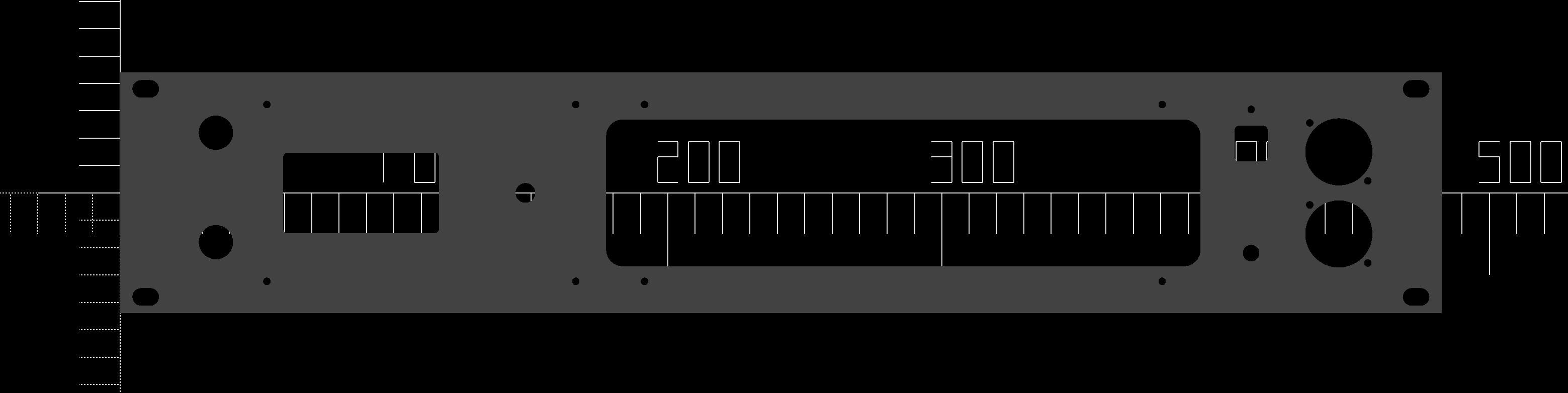
As OpenSCAD is able to output SVG, I also designed the panel graphics as part of the design to later UV print them at a local graphics shop.
I won’t explain how the code works here, but if you’re interested I’ve put all the code (as-is) in this repository.
The final parts that I sent to manufacturing are here, just in case you want to make exactly the same thing.4


As described in my OpenSCAD article, I had issues with circles in the DXF. I ended up discovering that going to SVG first, it was possible to get slightly better DXF files (the lines were connected) but not proper circles. Here’s the script to do that. I strongly suspect going via FreeCAD is a better option here. I will explain why proper circles were particularly important in this case in the next section.
Unlikely, but you can view the parts and see how it all fits together without having to render the code. ↩︎
Manufacturing
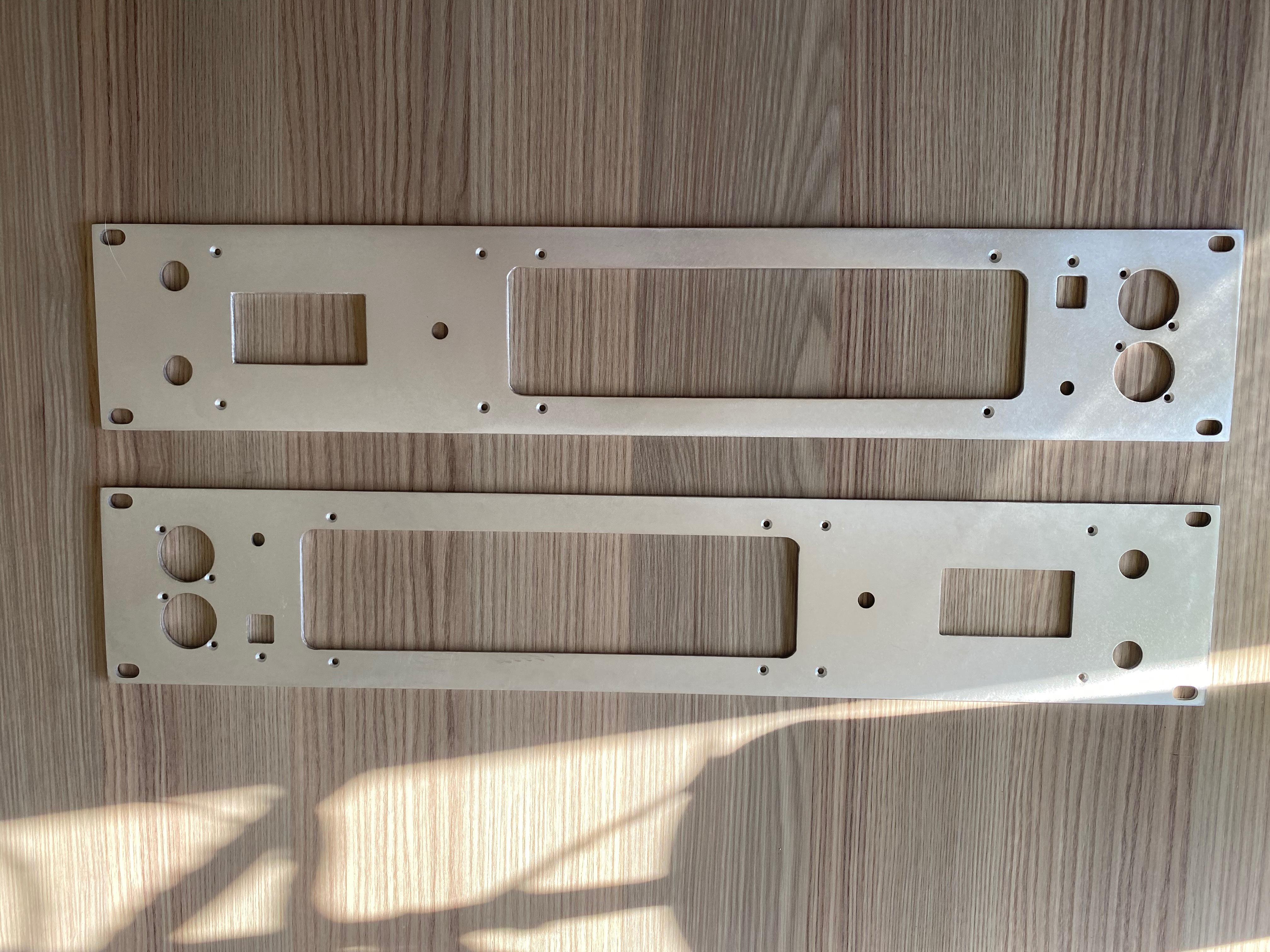
Panel metal
I discovered a local company that could CNC turret punch the face plate for me. This manufacturing method was news to me; I had never heard of the process before.
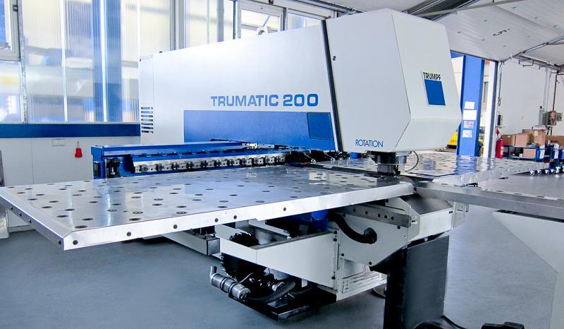
The workpiece is moved around, bolted to a gantry. There is a turret with a cassette of tools available. The CAM software optimises the selection and order of tools based on what’s to cut, picking (for instance) circular or curved punches for holes. The tools are pushed through the metal to shear out small chunks at a time.
Because a specific tool is needed for each piece of geometry, it’s not possible to do certain holes or curves. That meant I was asked to adjust the panel holes a bit to suit what the machine had – only by around 0.5mm or so, it did not matter.
The CAM tool selection was a big problem for me as the curves and holes that were produced by OpenSCAD were polygon approximations; the software at the workshop didn’t know how to associate tools for these shapes. I ended up using FreeCAD to infer circles by importing from OpenSCAD which is able to infer the proper shapes from the approximations.
Since, I’ve discovered OpenSCAD-DFX-Fixup which claims to solve this problem. I haven’t tried it but I would check that out if you’re in the same situation.
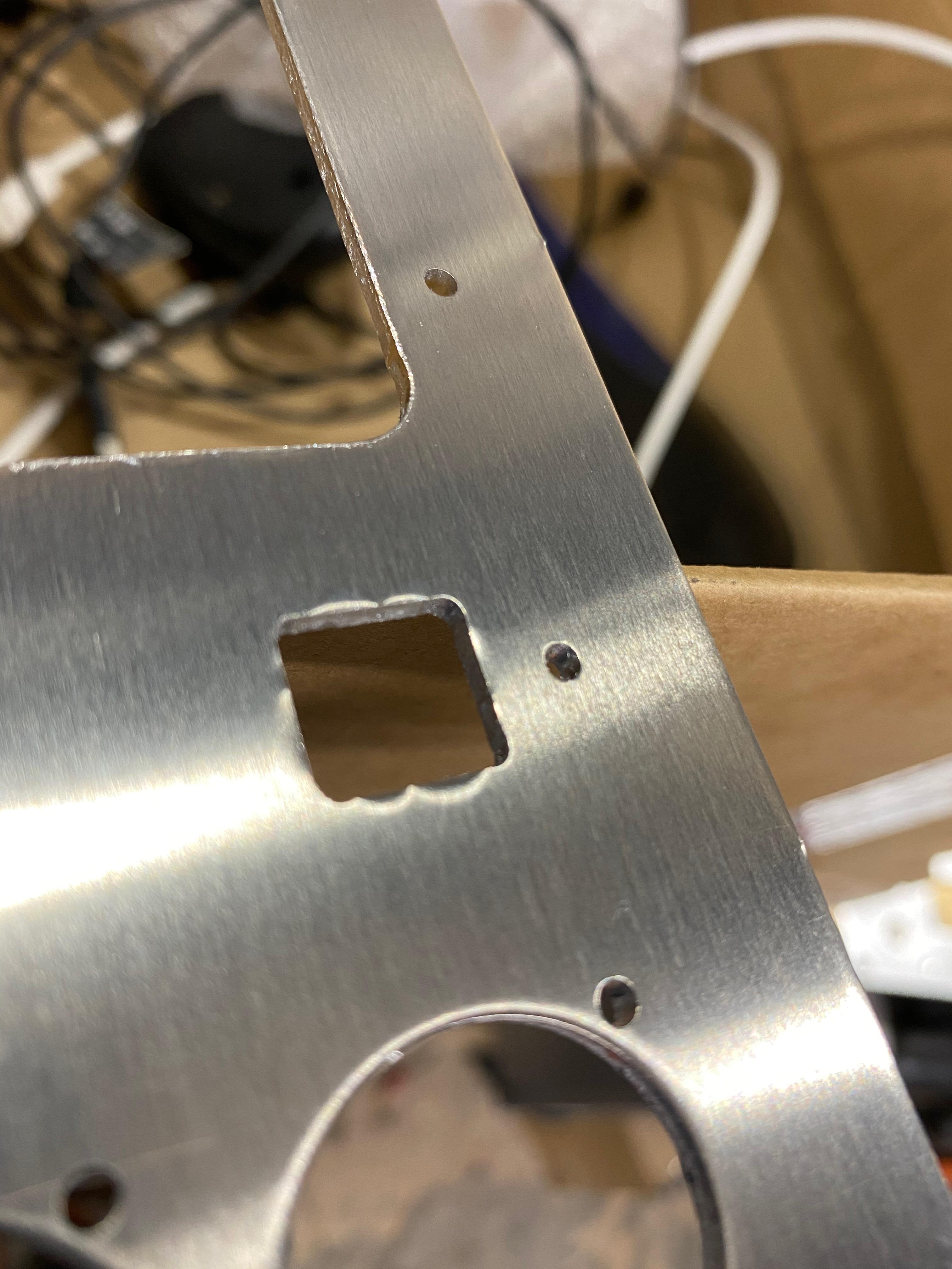
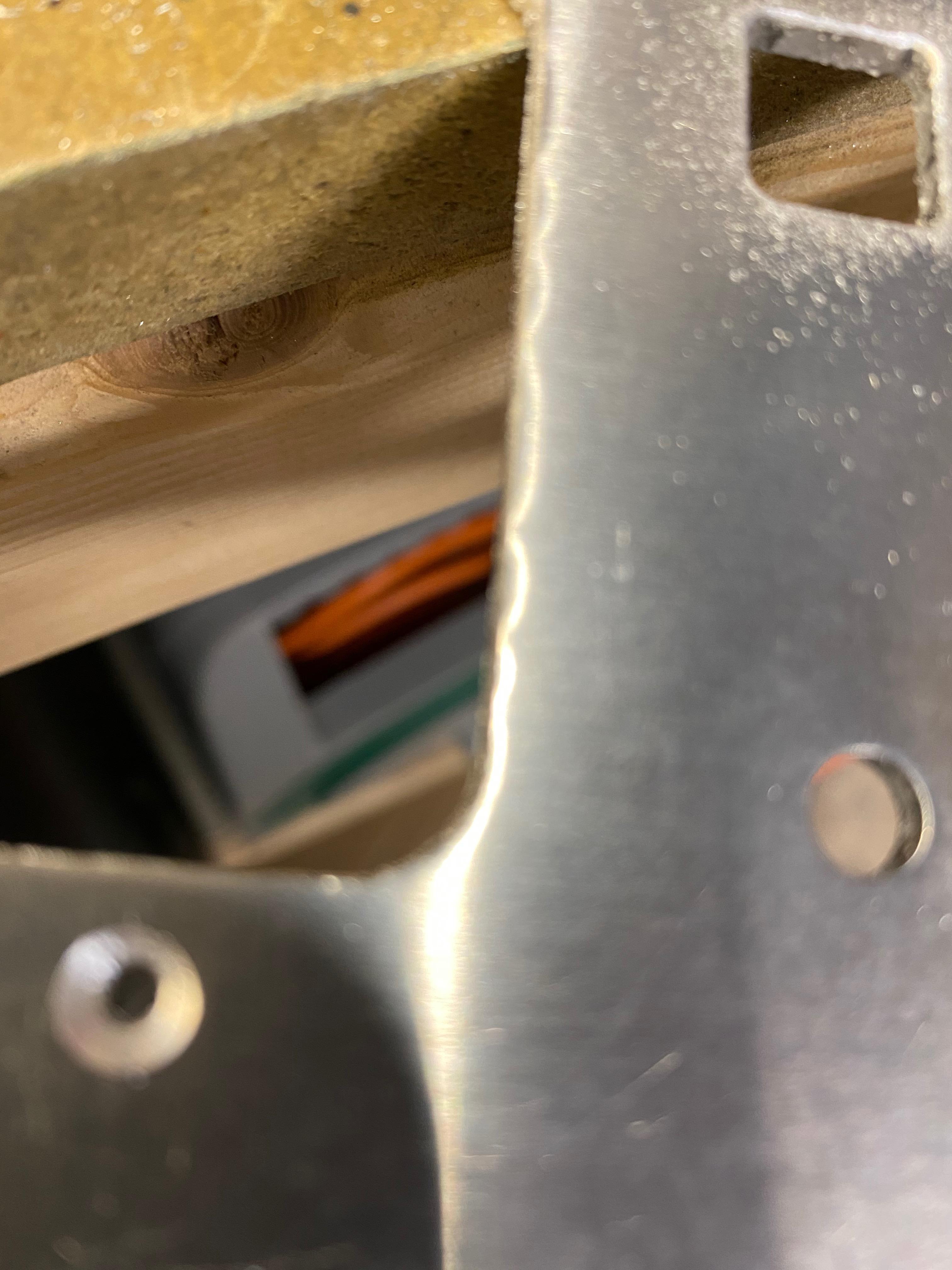
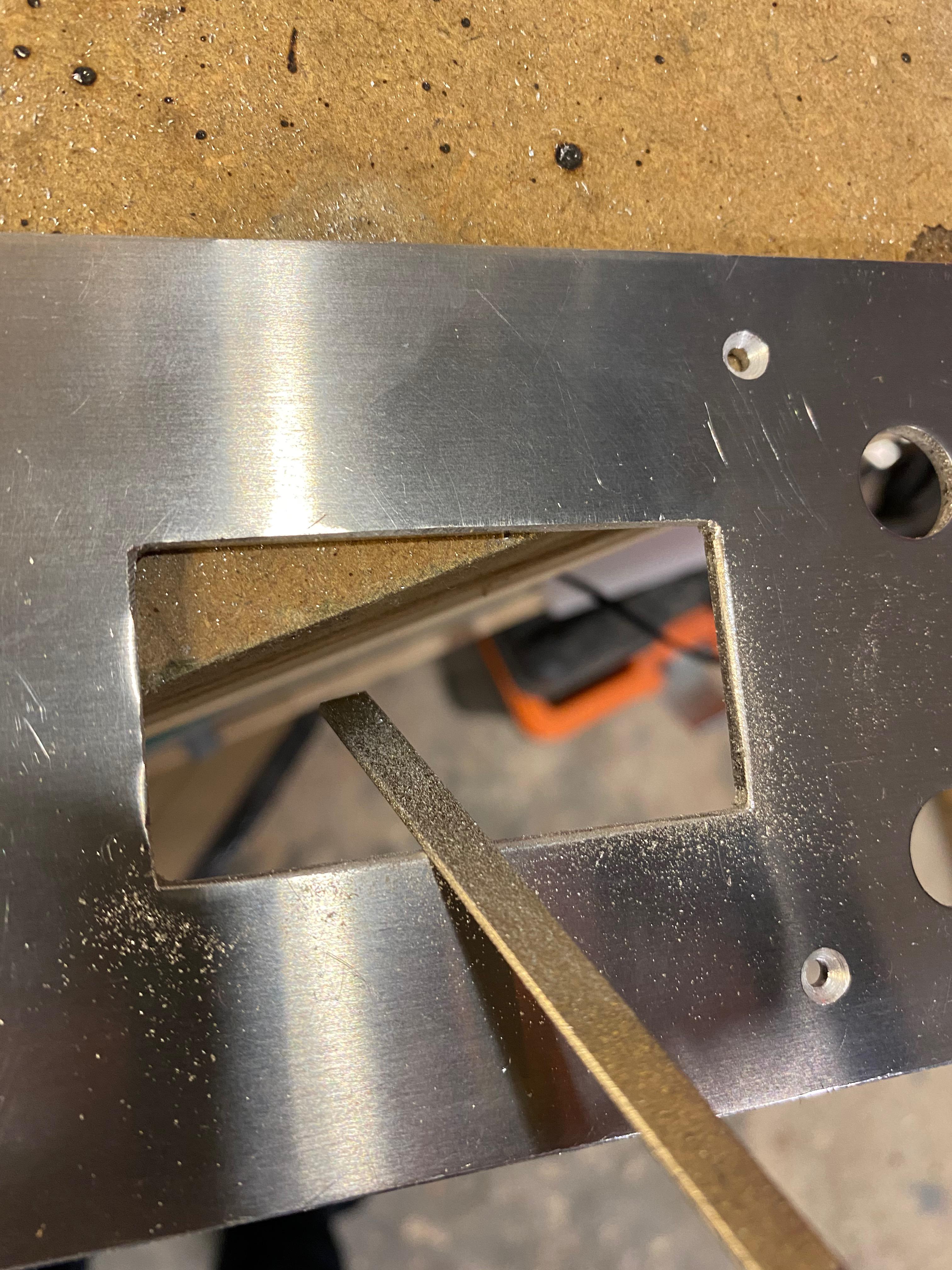
Due to the shearing process, there were quite a lot of apparent tooling marks and burrs. I started to file them off, but quickly discovered that sanding the plate with medium git sandpaper was much more effective and neater.
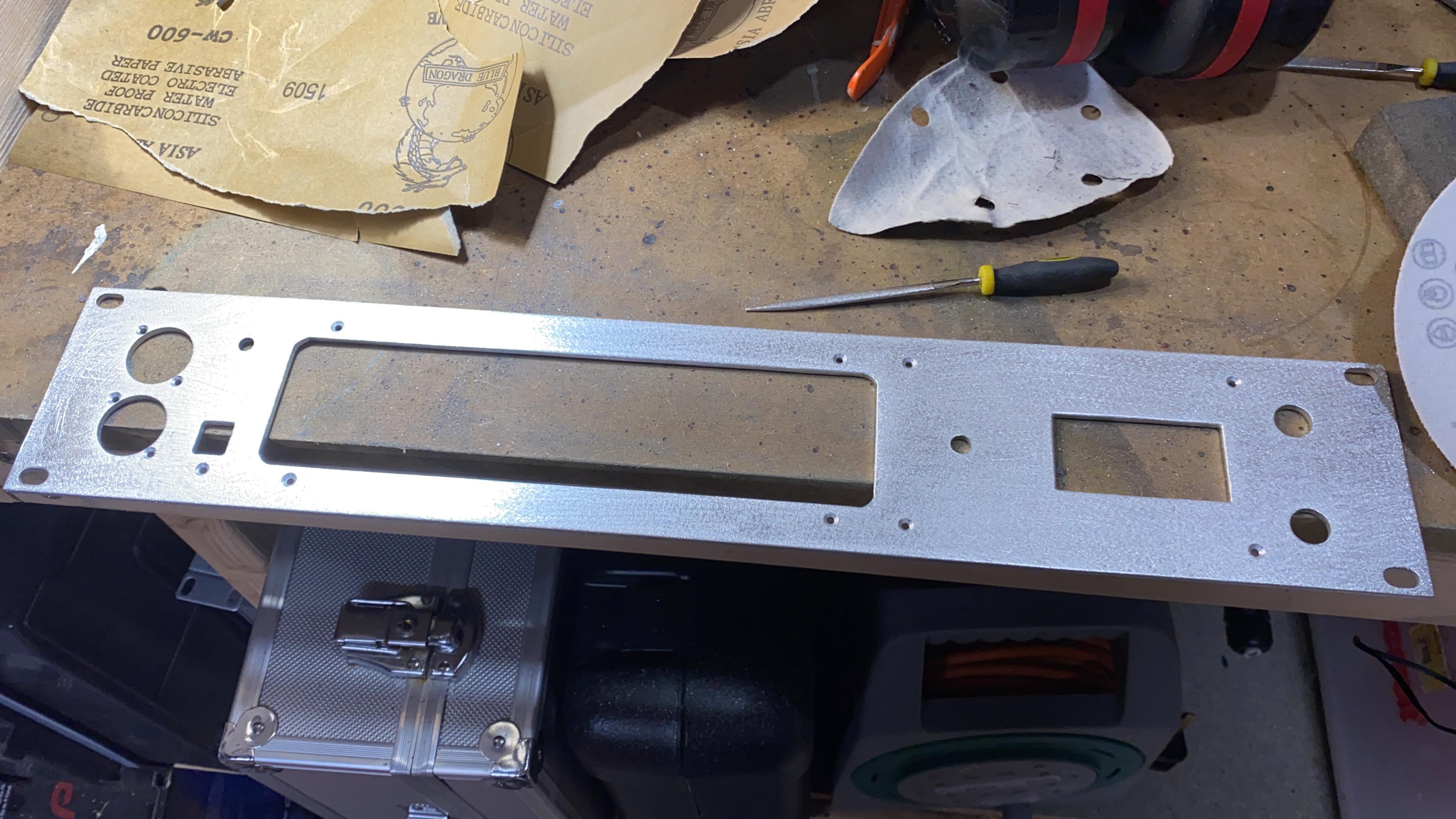
Panel painting
To paint the panels, instead of using rattle cans like I usually do, I thought I’d try a local auto paint shop. They gave me a good deal and put on some “2P” 2-part paint. The finish was flawless.
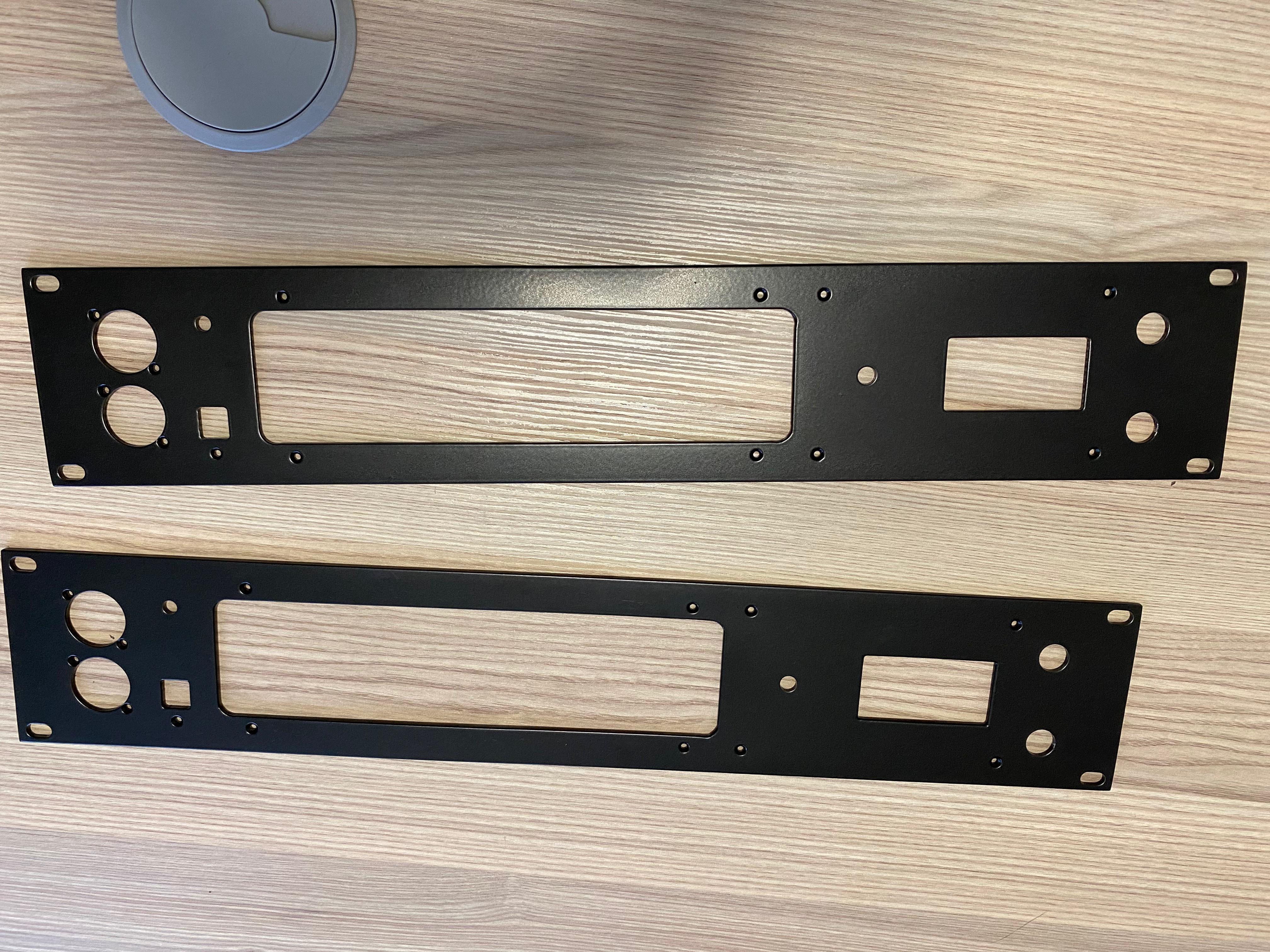
Panel graphics
I used a local company to do UV printing on the panel. I’ve had a great experience with UV printing at work – the finish is ultra durable and you’re able to print white too.
I converted the text and graphics from openscad to SVG which the company accepted.
I’ll admit I had go fever and didn’t put as much time as I should have into the graphics. I put simple text – it was sufficient but I could have made it look far better with some lines, logos etc.
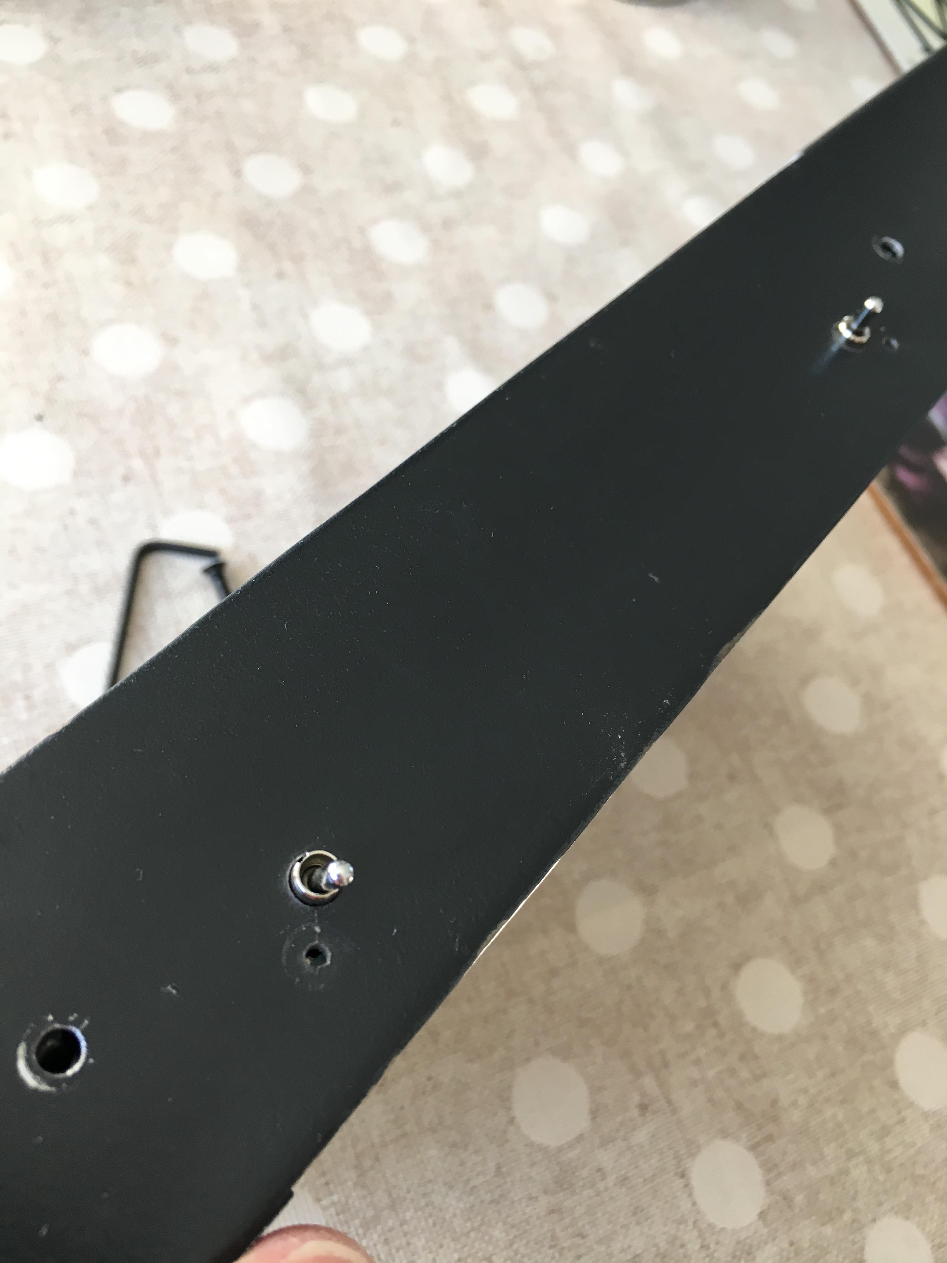
Switch boxes
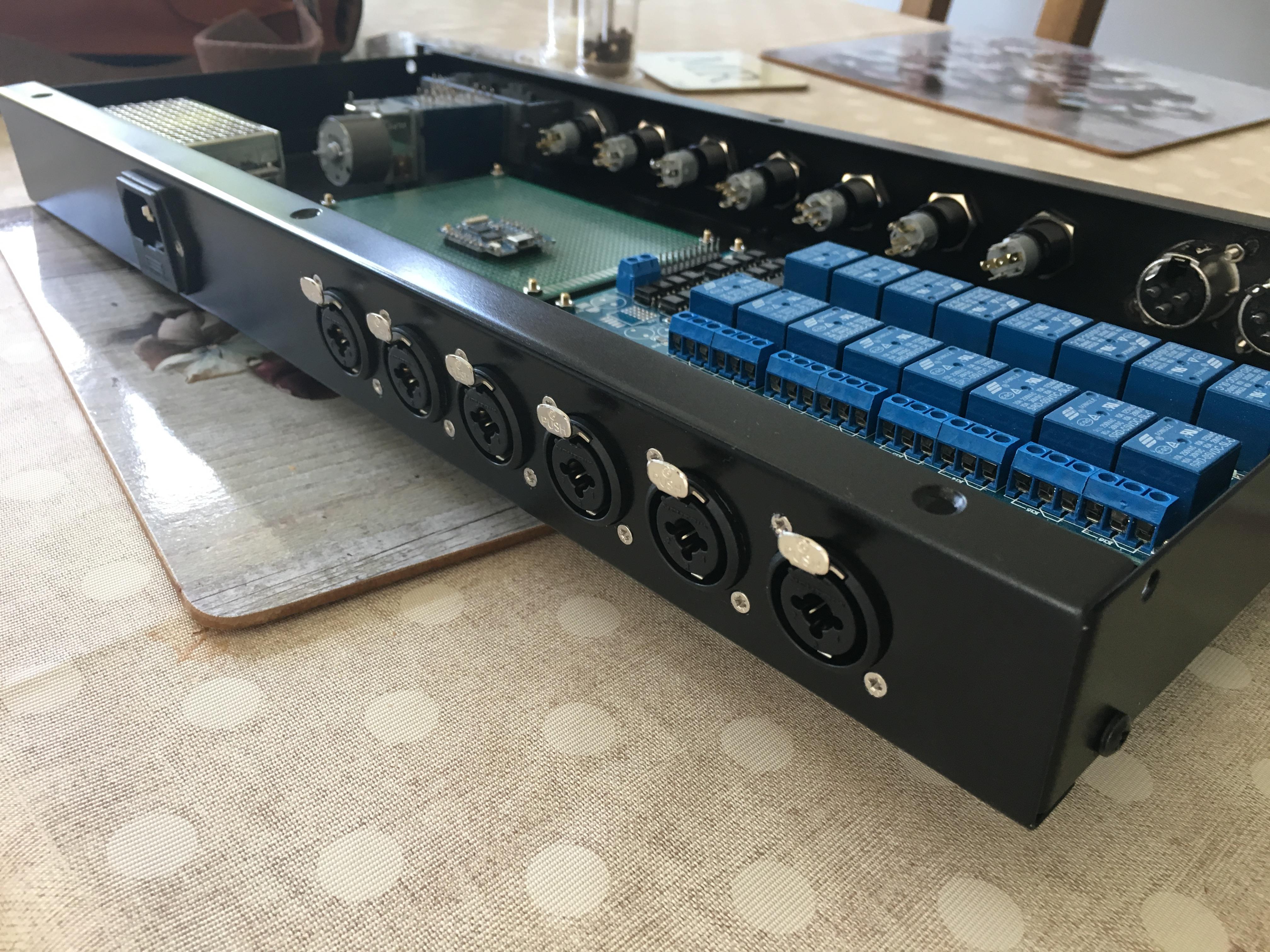
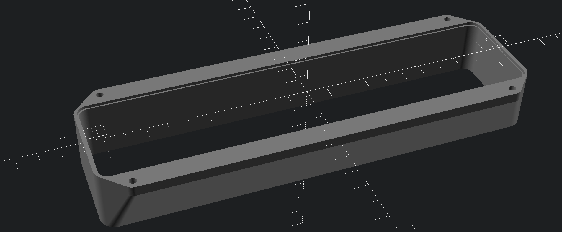
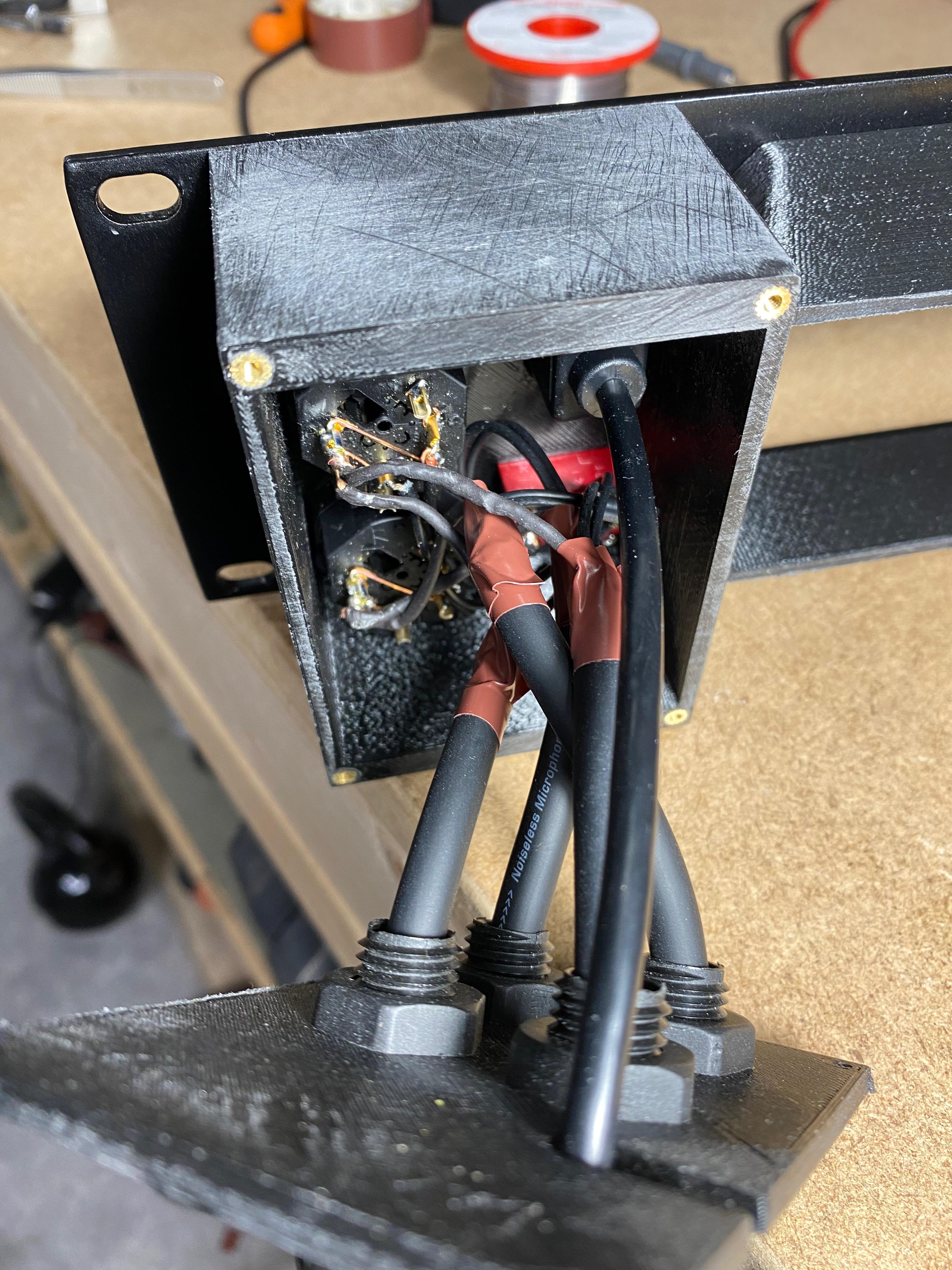
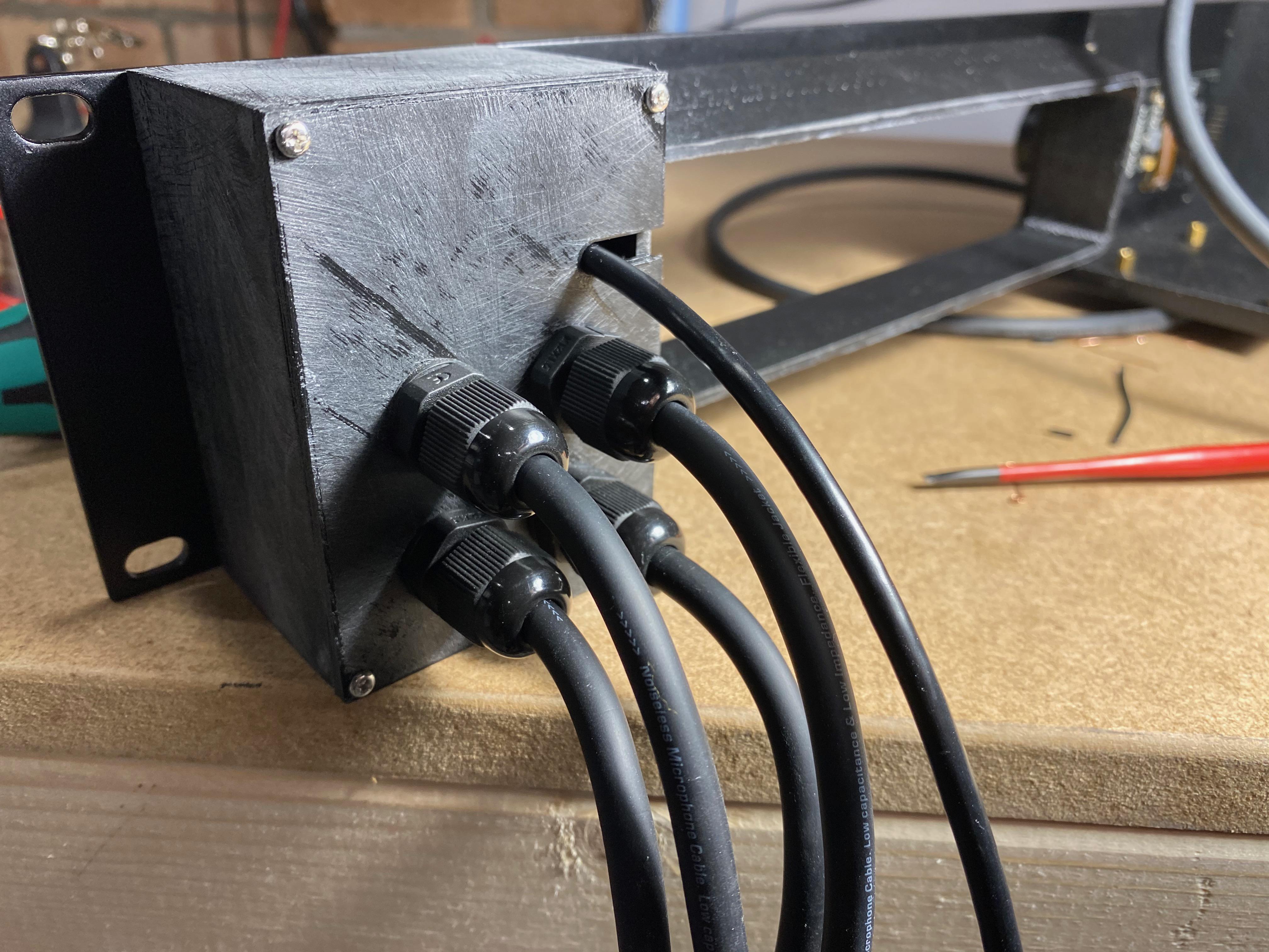
In addition to the brackets for the DAC and Pi/display, I made some boxes to house the mains on/off switches and the XLR/USB inputs.
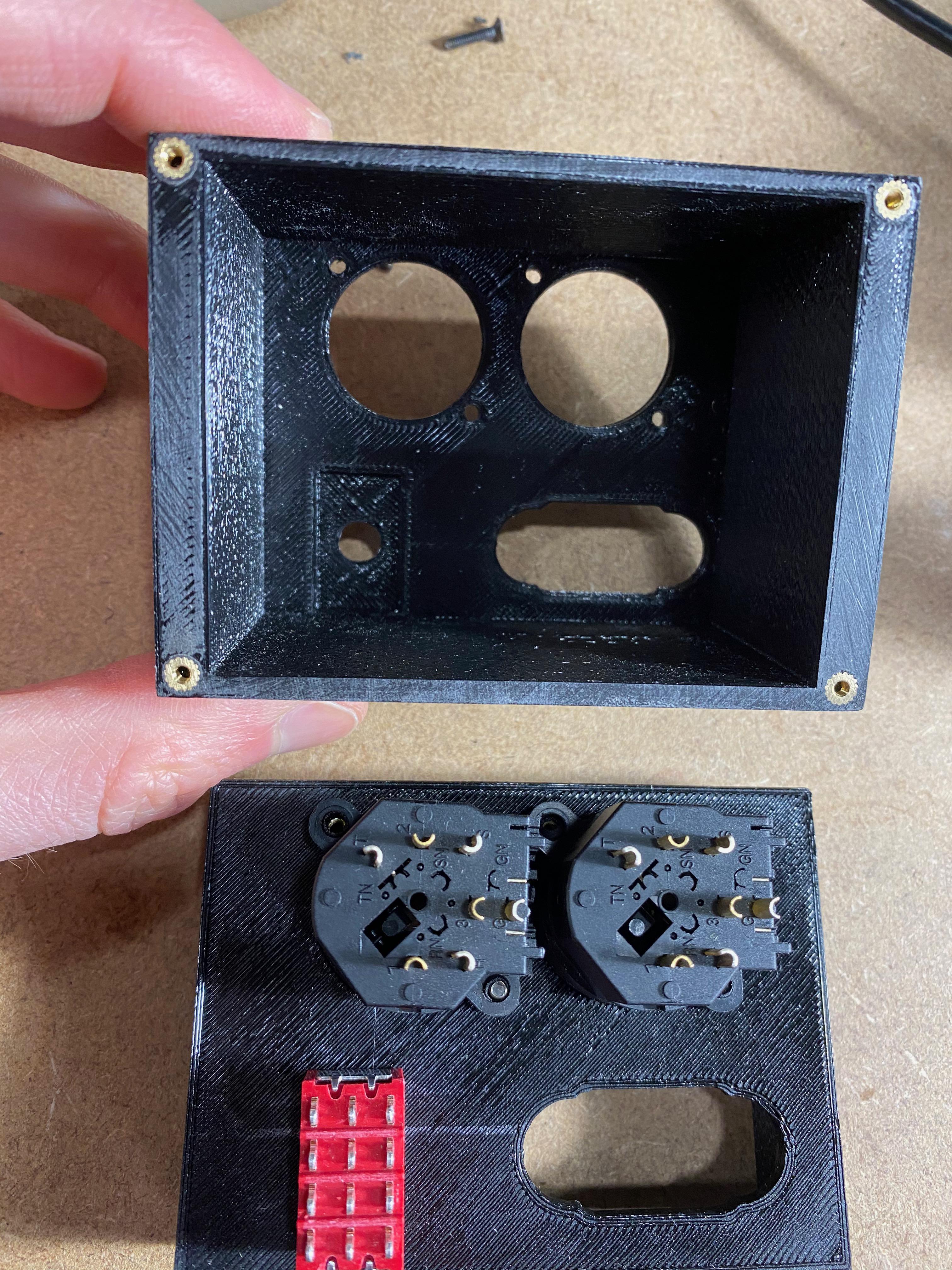
The general constriction method can be seen above – the front is attached via the socket bolts, the back via brass-inserts as described earlier. This worked really well to make the unit much more robust and hide the mess.
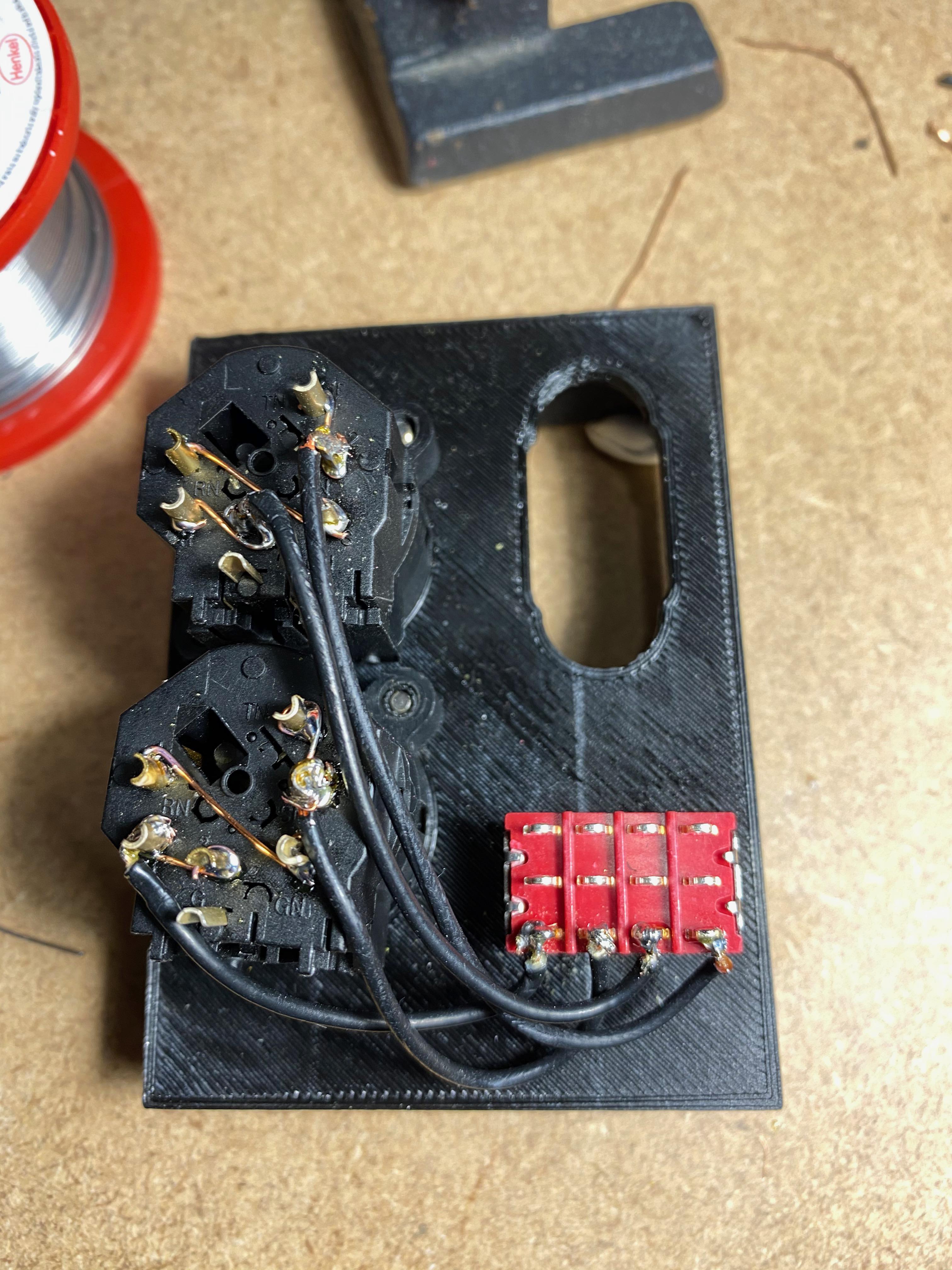
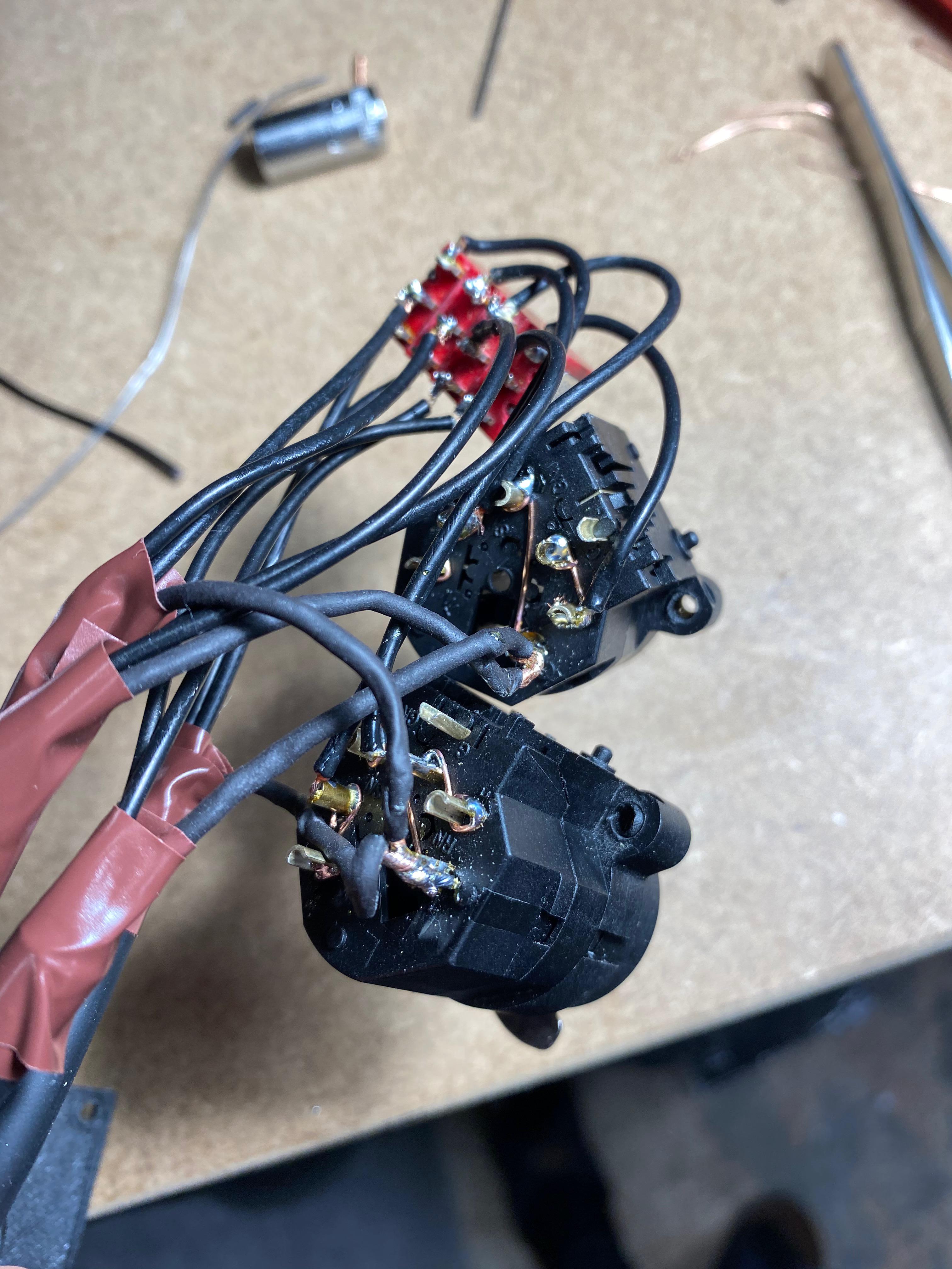
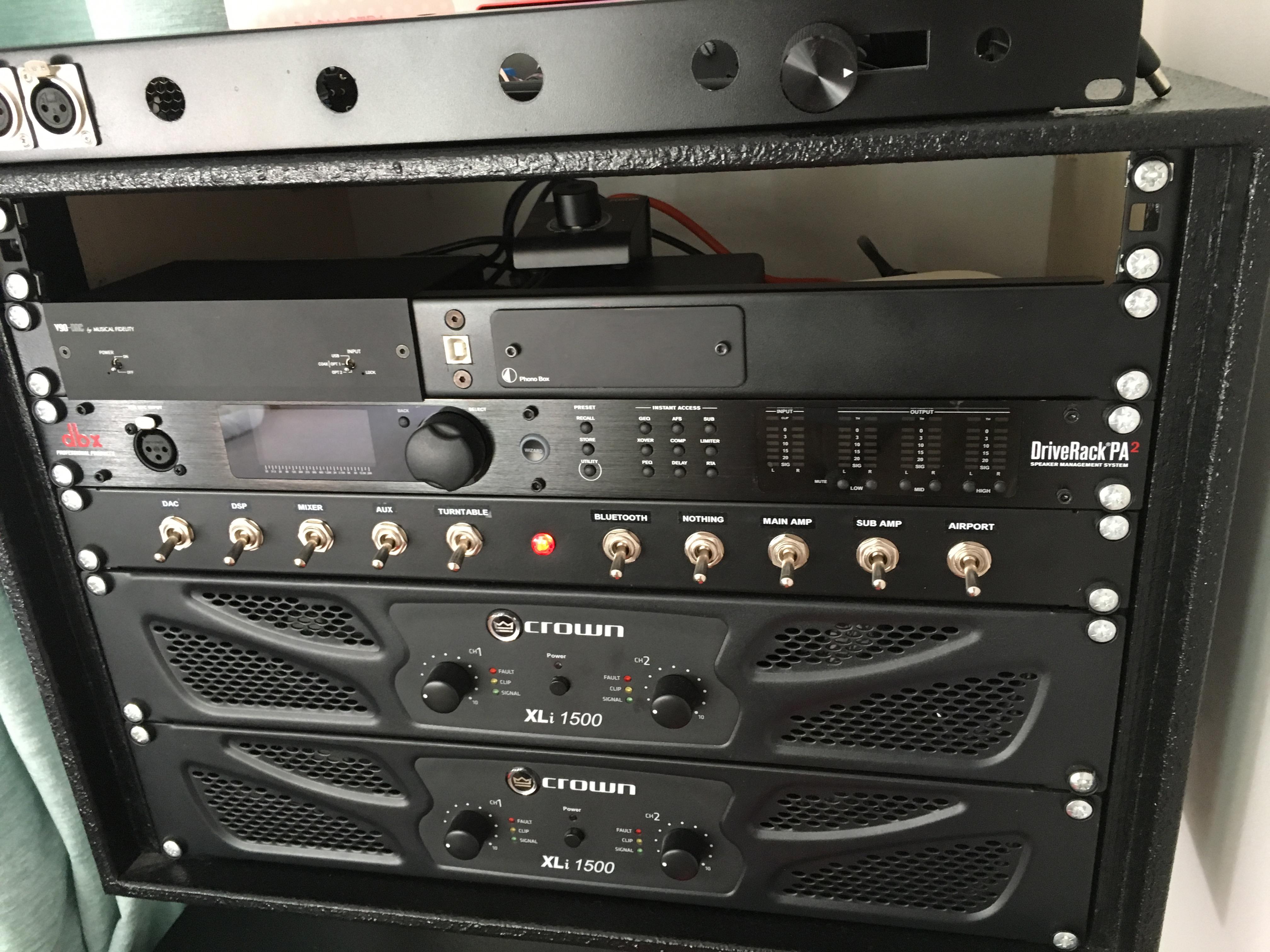
The red device there is a 4 pole 2 position switch. It allows me to switch the inputs of the DSP unit from the DAC to my DJ controller which connects to the XLR inputs.
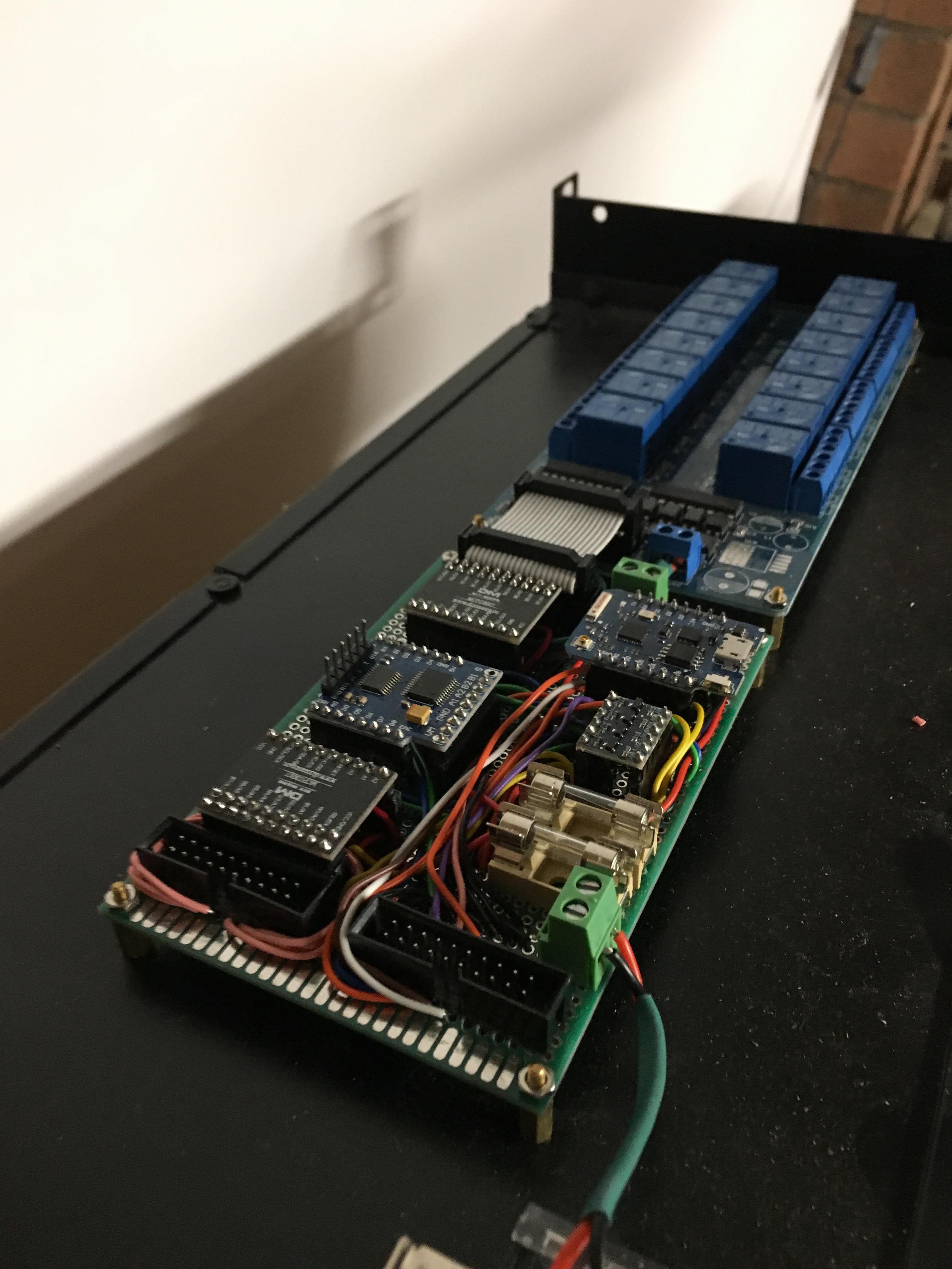
HifiBerry and modifications
I tried 2 HiFiberry hats, and settled on one with optical in and out. The optical out went to the DAC, and the input from the TV. That way, in theory I could get auto selection of TV vs Spotify and airplay.
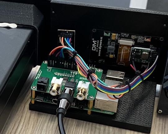
I connected the display and encoder with some dupont jump leads, intending to replace it with a custom ribbon cable at a later date. In the end I decided it was good enough as is.
HiFiberry has some provision for a rotary encoder built in. However the code used was polling based which resulted in a terrible experience using the dial – it would skip a lot and was slow. It also missed presses sometimes too.
To fix the rotary encoder issue I wrote some volume controller threaded python code to do this. I never got around to upstreaming this, so if you end up using it please do on my behalf.
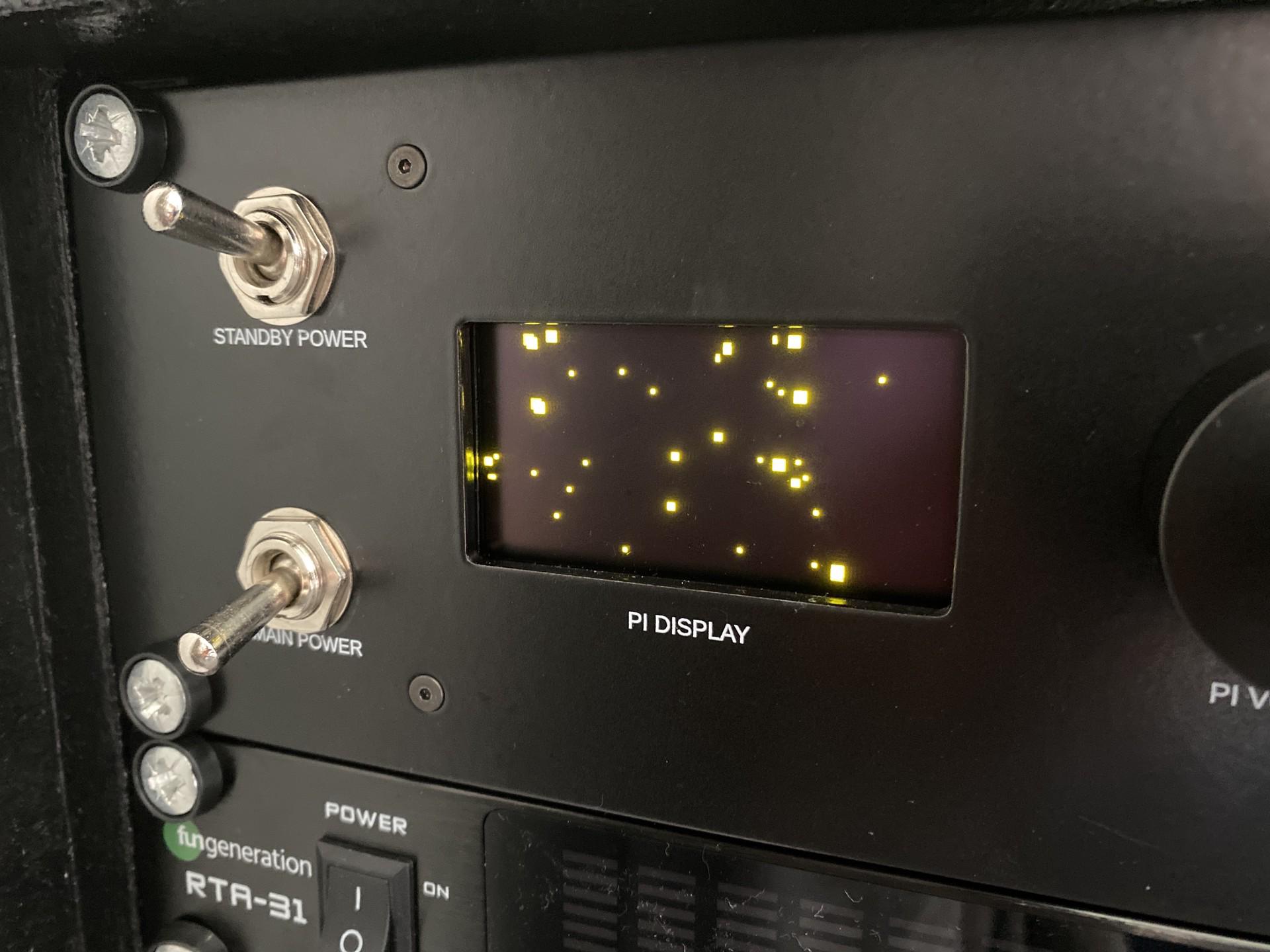
To test the OLED display tried some animations built into the luma OLED library I used. I never got round to implementing the track information display, just an indication of the current volume which was useful at least.
I have to say though, I was disappointed with the HiFiberry. In concept it’s great. However I ran into a lot of reliability issues when using it with airplay or as a spotify speaker; these things should just work, else they’re frustrating and worse than simply using a cable.5
The volume control was also apparently linear instead of lograrithmic like it should be. This meant that the volume control was sensitive at low volumes and not sensitive enough at high volumes.
An analogy: Home automation. Don’t replace a hard wired lightswitch which works 100% of the time with something “smart” that has dozens of single points of failure. More tech doesn’t mean it’s intrinsically better, it’s just bad engineering. ↩︎
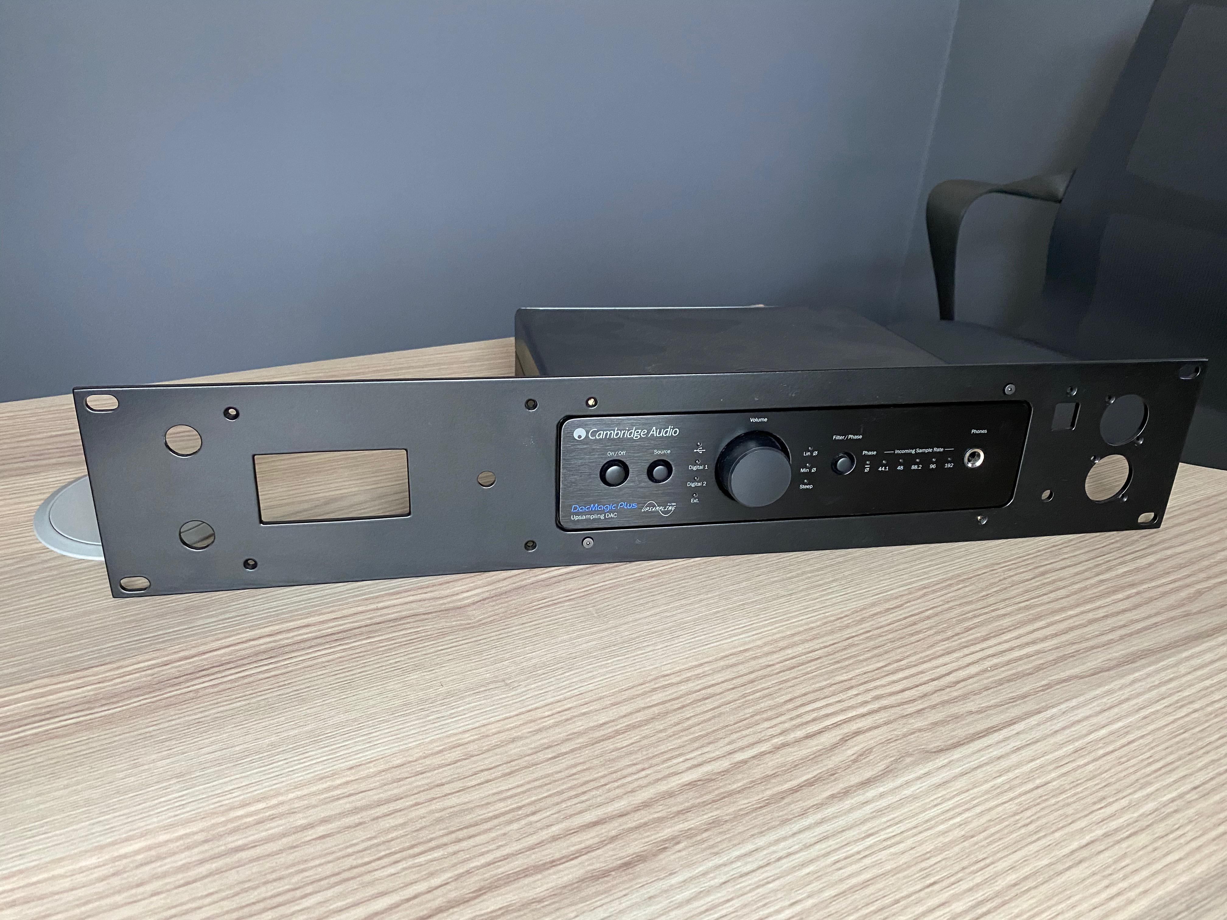
Putting it all together
Thankfully everything fit together first time; albeit the large DAC bracket was tight. I think this could have been due to shrinkage, but more likely due to poor tolerances of my old 3D printer.
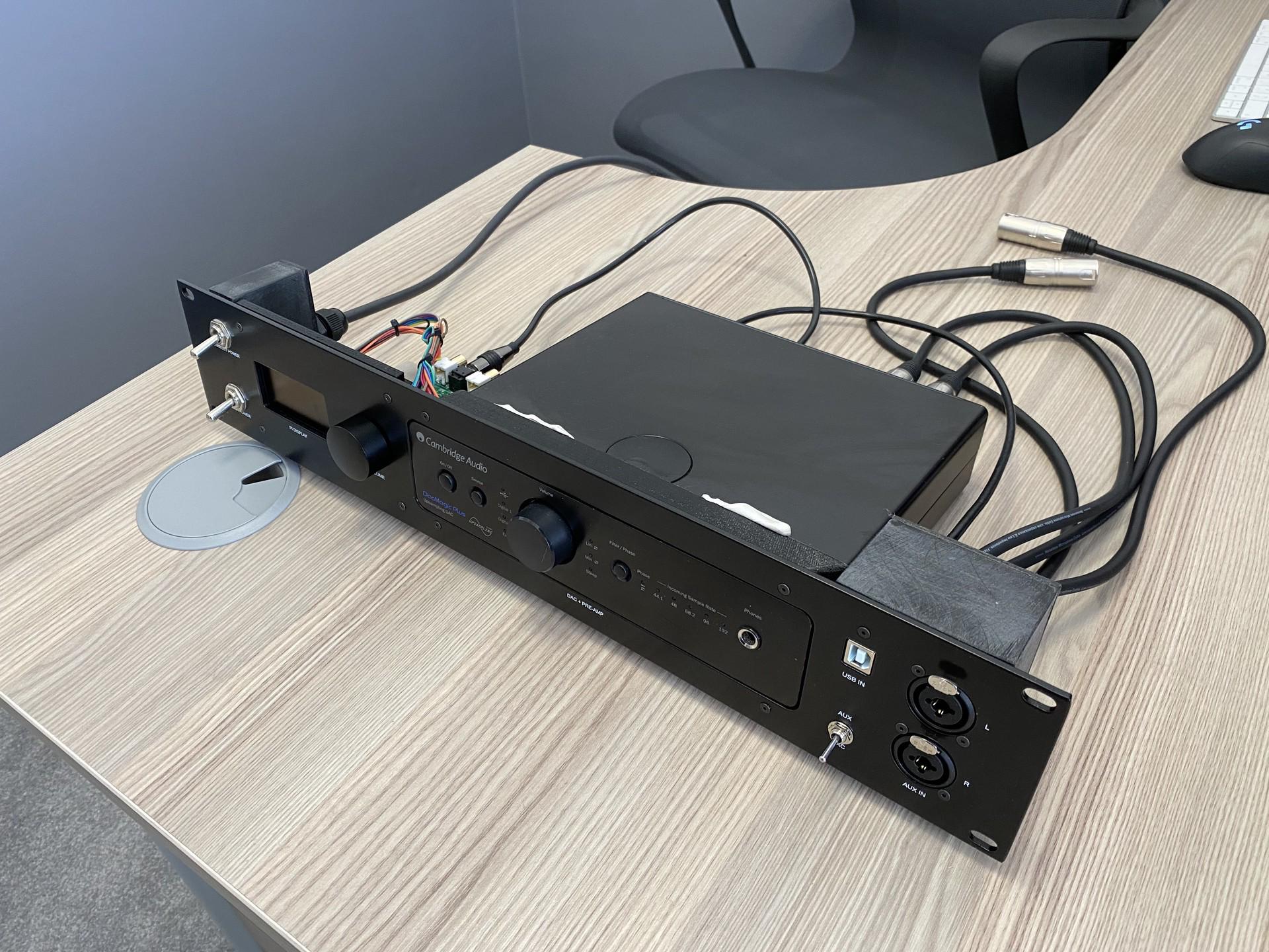
Given there was nothing but the brackets to stop the 3mm aluminium from flexing, the assembly wasn’t as solid as I’d hoped for. Solid enough, though.
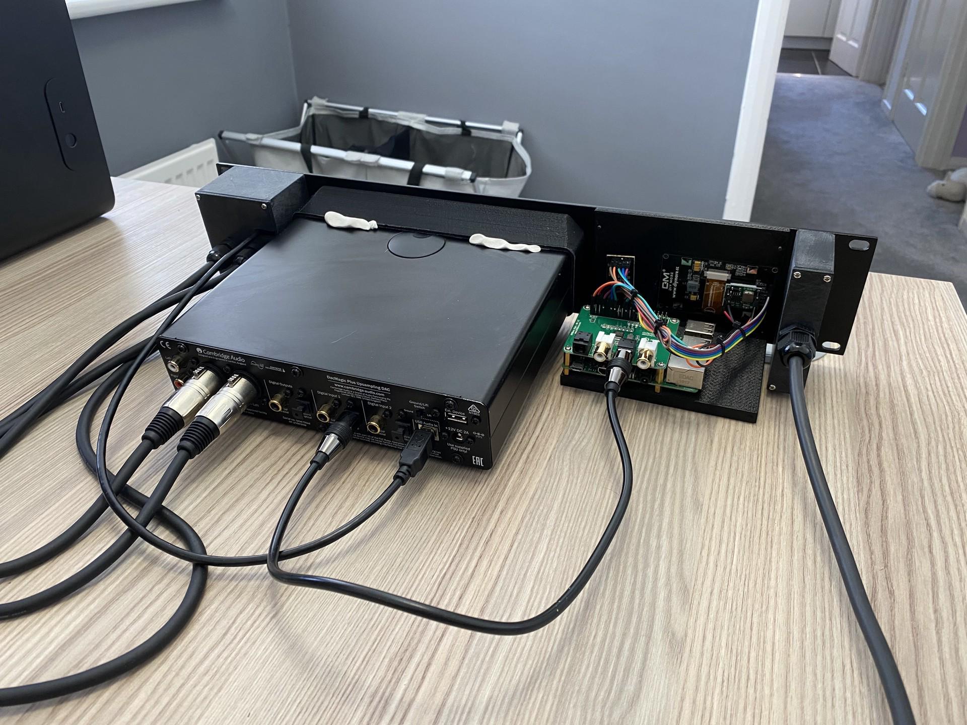
I used blu-tack to prevent the DAC from moving out. Given it was positively retained from moving in by the face plate, this was fine. A good idea as it was easily removable.
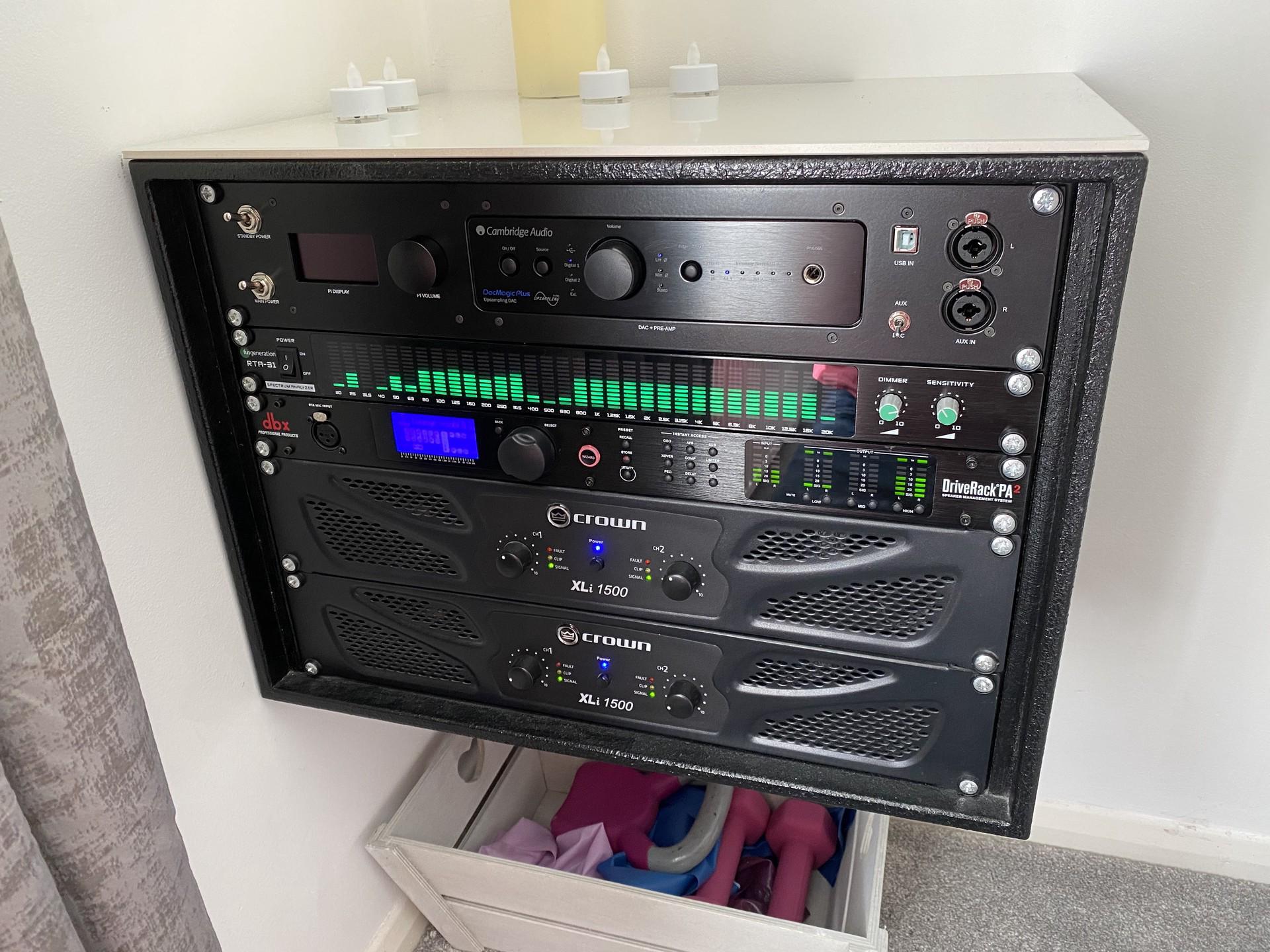
My eventual solution
In the end I abandoned the HiFiBerry, DACMagic (and Driverack DSP) in favour of a Wiim Pro which is more reliable, and has a 12V trigger output which I wired straight to a beefy relay to turn on the power amps.
The new DSP resulted in undeniably better sound quality and the Wiim pro, while not perfect, is far more reliable.
I kept the spectrum analyser though, as it’s rather interesting to associate bass notes with particular frequencies.
Conclusion
I have released the code to everything you see above in a github repository. It is supplied as-is without much documentation.
It’s possible to rackmount nearly anything if you can sink it into a face panel somehow. It’s a great thing to do but high effort (and cost) the way I did it – a problem if you tend to change your gear around a lot like me.
OpenSCAD is suited rather well to lay out the components, holes, support hardware and graphics all in one view. It is unfortunately not suited at all to a CNC turret punch simply because curves (arcs) are not properly represented in the DXF output – the machine therefore fails to find the right punch tool!
Given my previous article I think I’d be better off 3D printing a rack conversion next time. The challenge would be to make it look just as solid and professional as the metal one – perhaps I could hide the necessary joins into the design and make the panel thicker to compensate.
Given I now have a 3D printer able to print multiple colours, I could use a 0.2mm nozzle to embed (possibly backlit) graphics into the print itself. Alternatively I could use my laser cutter to vaporise a coating of paint to reveal the plastic colour underneath; there are may videos such as this one on Youtube that show how to do this.
Thanks for reading! If you enjoyed this article or have comments, please consider sharing it on Hacker news, Twitter, Hackaday, Lobste.rs, Reddit and/or LinkedIn.
You can email me with any corrections or feedback.
Tags:
Related:

