
Large horn subwoofer build, for mountains of bass!
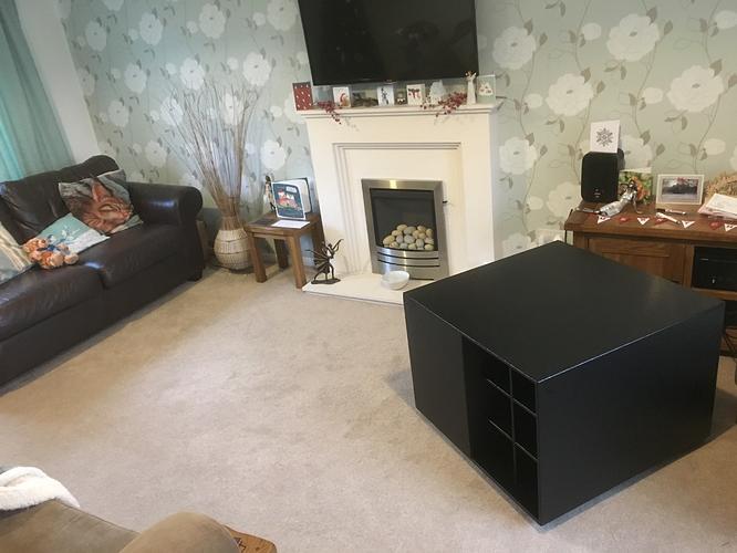
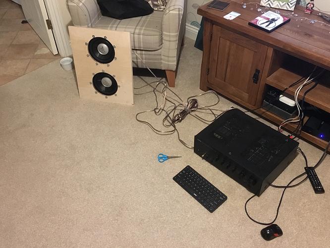
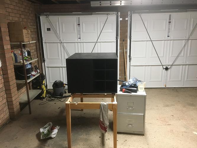
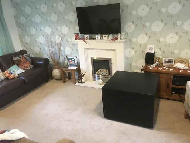
A few years ago I built a massive folded horn subwoofer that now lives in our lounge. It’s approximately the size of a refrigerator, and will happily produce bass that can distort your vision!
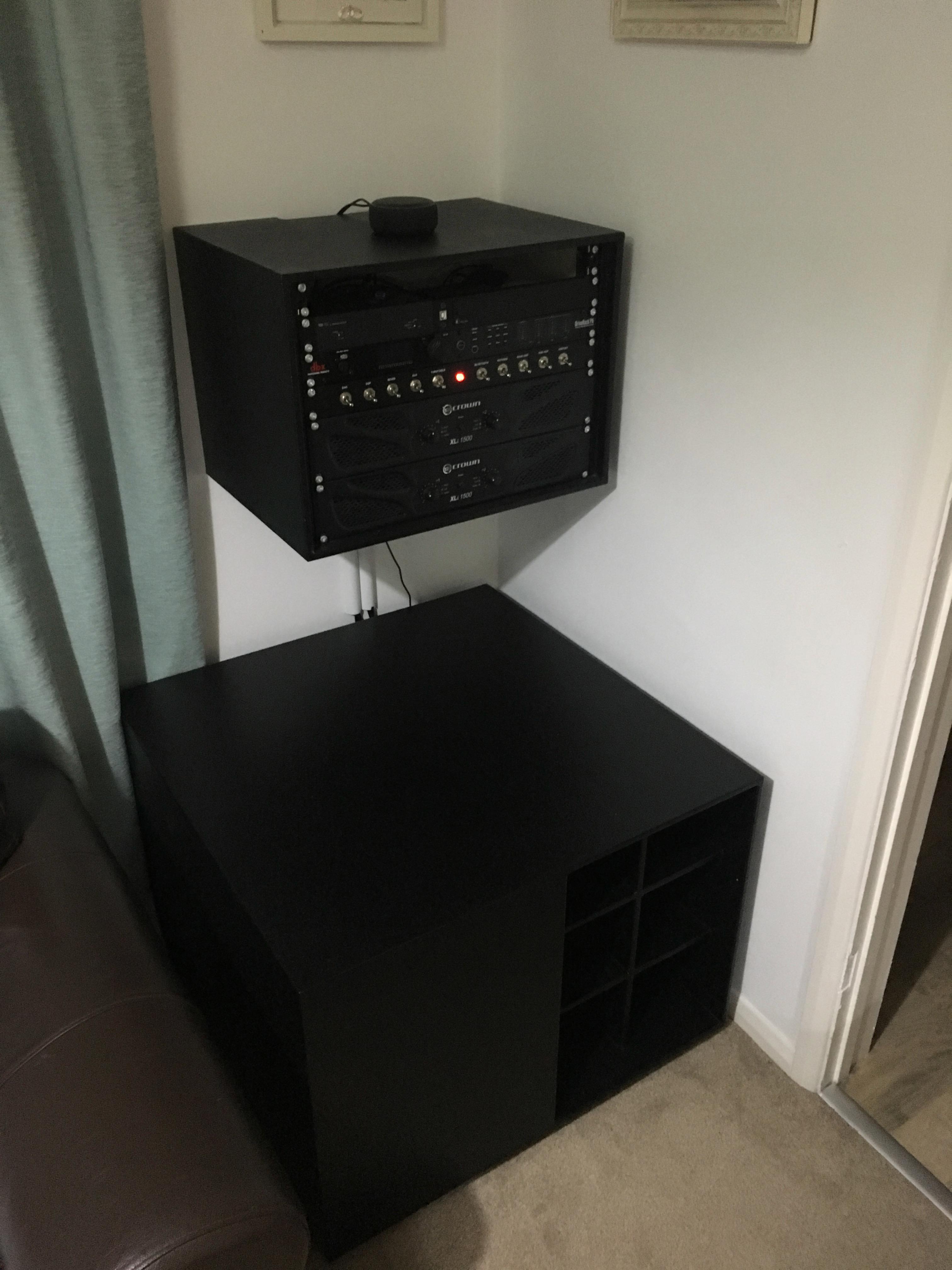
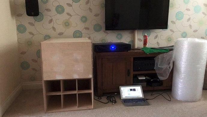
I’ve now paired it with a DBX Driverack PA2 to do the crossover and DSP, together with 2 Crown XLi 1500 PA amplifiers. One amplifier powers both subwoofer drivers, whilst the other powers my Mission SX2 loudspeakers. The PA2 is currently fed by a Musical Fidelity v.90 DAC, though will soon be joined by another project of mine that I’m yet to write up which is a microprocessor controlled balanced input selector/attenuator.
The subwoofer itself is a design by Bill Fitzmaurice who sells plans for a selection of loudspeakers – mostly horns. The design I chose was a Dual Table Tuba with 2x 8" JBL GTO 250W RMS bass drivers, which had the compatible Thiele-Small parameters and were widely available at the time. Despite their small size, they are a good match for the horn as they have a considerable maximum excursion and can deal with the high pressure within the horn.
Horn loudspeakers are relatively efficient, as they allow the loudspeaker to couple to the impedance of the air much more effectively. This means that for a given input power of another design (such as infinite baffle or bass reflex) they will produce more audio output power. As with everything though, there is a compromise. In this case it’s physical size (and weight!) though, as the horn is folded the space utilisation isn’t bad.
What follows is the edited version of my build log, mostly circa 2016. As the build log was on a private forum, there were some questions along the way mostly from James Reuss or Phillip Martin. I’ve left them in with my responses. The project actually spanned 3 houses over 3 years!
Breaking in the drivers
As the plans recommend, I broke in the drivers overnight with a 27Hz (near resonance) sine wave for 12 hours at about 1cm excursion and about 8v RMS.
I used sox to generate the signal. The command was: play -n synth 43200 sin 27
Did it make a nice hum?
No actually. The sound was mostly cancelled out due to the interference from behind the cone, could barely hear it. And bad acoustic coupling/impedance matching.
Surely you could just plug the mains into it for a nice pure 50Hz sine wave?
Maybe later.
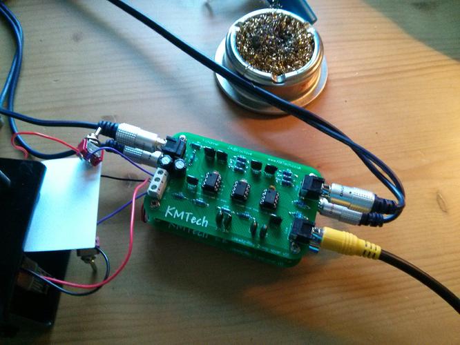
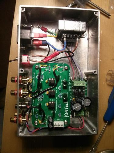
Some time later, I thought I’d make a crossover. I got a kit from JMtech on ebay. I packaged that up into a project box and used it as my main crossover with my old HiFi for some time. This build is documented here.
Starting the build
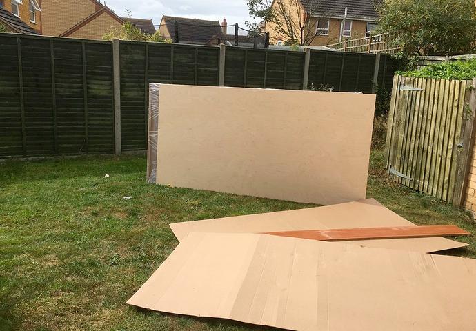
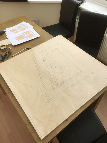
Eventually I got round to ordering the wood. After my brother laid out the cutlist for the panels on CAD software, I ordered 2 sheets of 2440mmx1220mm 12mm baltic-birch plywood with a single 600mmx1220mm extra panel. Baltic birch is the finest grade.
- I ordered a second driver because most amplifiers have 2 outputs, and more bass is always preferable.
- It was broken in after an overnight sine wave
- I borrowed a circular saw
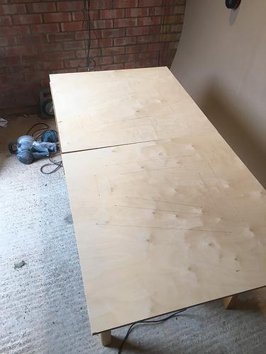
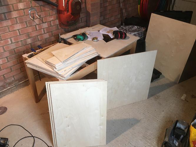
- 12mm Baltic Birch Plywood was delivered – 6.5 square metres. Huge panels, and reassuringly heavy. Moving each panel was a 2 man job.
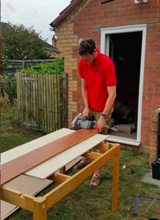
Here, my brother and I are trying to figure out the optimal number of beers to make perfectly square circular saw cuts:
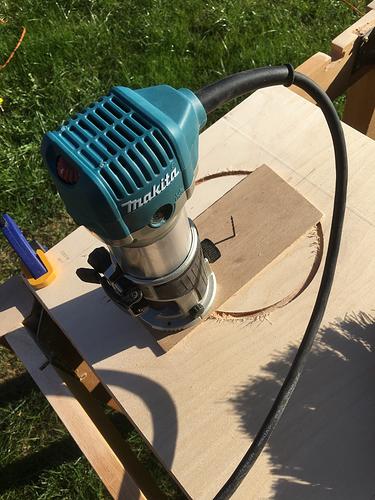
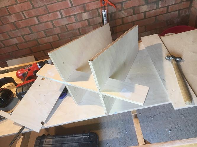
Marking and cutting the folded horn side panel:
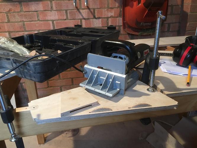
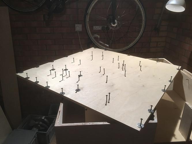
Using tornado-type nuts, I practiced on a scrap piece first. I used a router circle jig made from some thin ply.
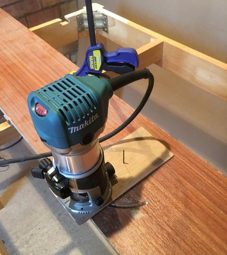
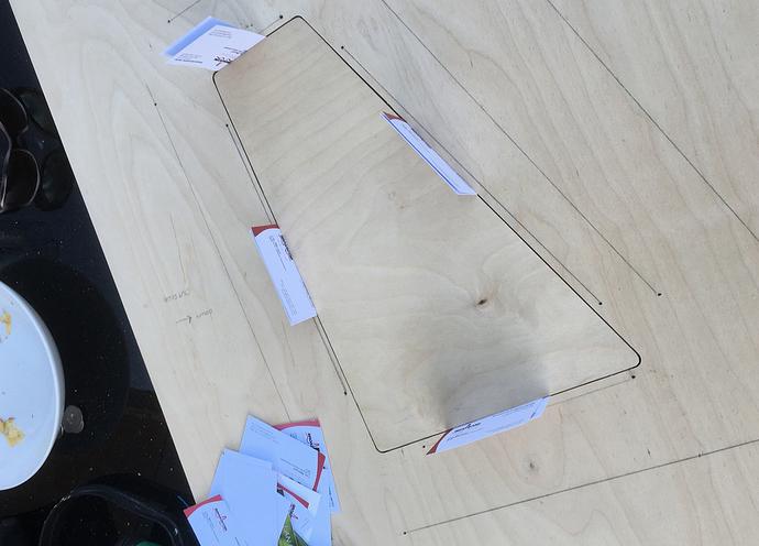
The access cover was fitted precisely using cards.
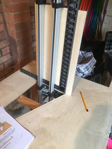
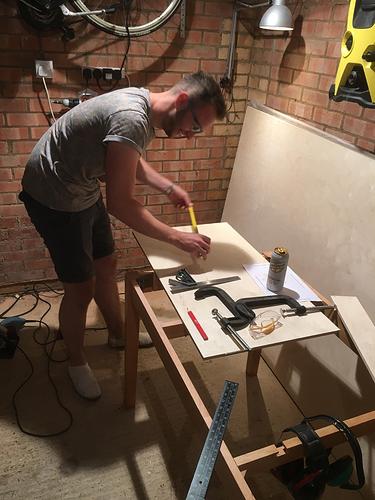
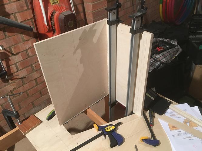
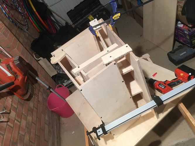
It was important to get everything as square as possible. I used a carpenter’s square and a few sash clamps for the first panel.
The plans say that butt-joints are adequate due to the ultra-high strength of the polyurethane adhesive. However, biscuit joins are better so that’s what I did. Note that I couldn’t source reasonably priced Loctite PU-premium as mandated by the instructions, so I used Evo-stick Polyurethane wood adhesive instead. This has similar expansion properties and worked great!
Size zero biscuits seemed best for 12mm ply. I had to adjust the calibration screw a bit.
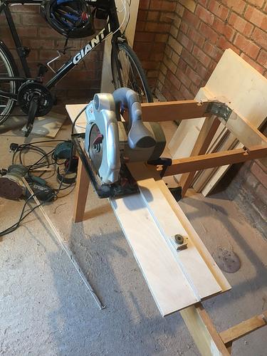
I made a sled for cuts without offsets. It was rather useful:
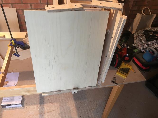
Note some warping, which is expected and will be dealt with via clamps and jigs.
Some tips:
- Make a circular saw sled, it will save time
- Watch motor clearance on the circular saw; if it catches on something it can cause wobbly lines and burning. It seems obvious, but it happens more than you’d think.
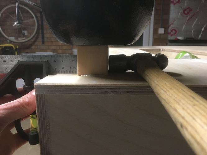
- For guides: Mark, set, measure for squareness and tap with hammer to align
- G-clamps suck. Get IRWIN Quick grips or something.
- Mark a workpiece clamped to the table, much more accurate.
- Get an old table and remove the top to reveal a great cutting stand
- Cut until the entire blade has passed the end of the wood to avoid strange artefacts (with a cheap saw?)
Near-disaster
The plans recommend temporary jigs. The polyurethane glue sets fast and is incredibly strong. I just about managed to chisel off the jig after about 5mins, which damaged the wood by taking out a few chunks. Damage is superficial and internal only. I coated the voids with glue.
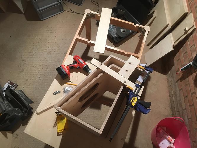
Note that I used the recommended temporary cabinet screws with penny-washers to provide the clamping forces throughout the build. This reduces the number of clamps you need and is extremely effective.
Here’s my technique:
- Dry fit the panel, with Jigs or clamps
- Drill through the joints, root (minor) diameter (2.5mm) for the length of the (40mm) screw
- Drill, using a piece of tape as a depth gauge, one panel thickness in the same hole, thread/major diameter so the screw does not bite the first panel
- Remove panel and jigs/clamps
- Apply washers and screws up the depth of the first panel, waiting to accept the panel flush
- Apply a 3mm or 4mm bead of glue
- Apply panel by eye
- Screw in one side at a time, using a power drill with slip clutch of predetermined setting. Do not tighten screws yet
- Tighten screws and wait overnight for glue to set
- Remove screws and maybe fill voids
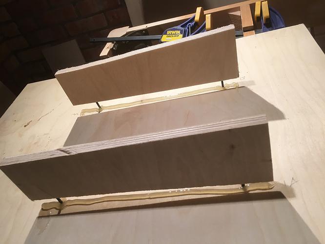
Removing squeeze-out with chisel and hammer:
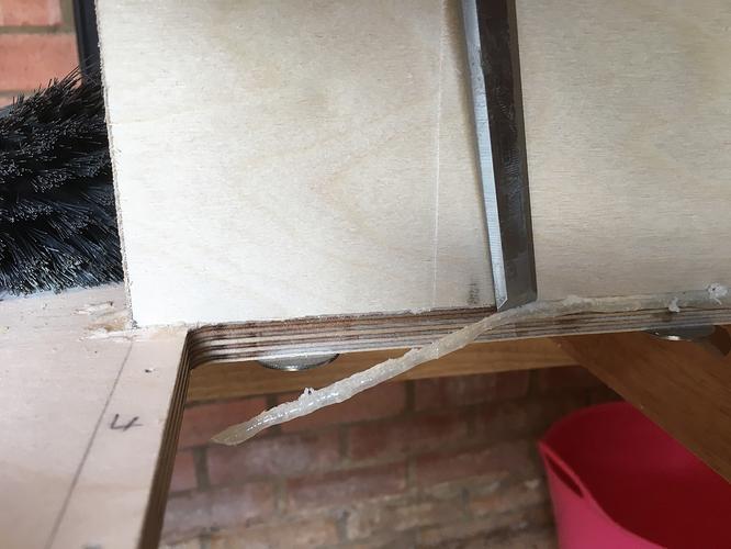
Squeeze-out means that you can be sure the glue has coated the entire joint; so it’s not a bad thing. Ideally, you want a small amount.
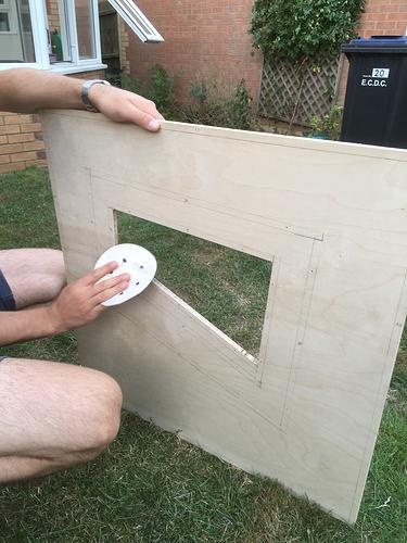
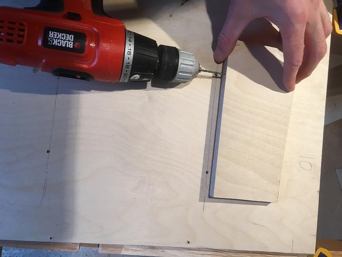
Cutting the baffle
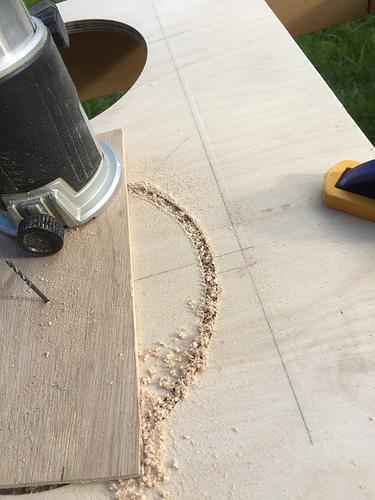
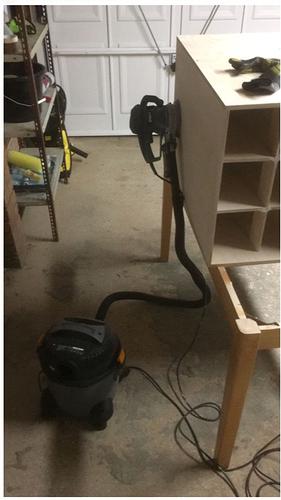
Go fast enough such that you get large wood chips as shown; to me it felt unnaturally fast – too slow, and you’ll re-cut the chips and burn. For the same reason, you must get rid of the sawdust with a brush or take-off vac on the fly.
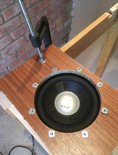
Tee nuts are now epoxied in. Use an identical diameter drill bit, rather than a slightly smaller bit, so it isn’t too difficult to pull the bolt through.
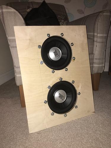
Curiously, one driver had smaller holes than the other meaning M5 bolts would not fit. In the end, this gave me the idea to ream out all the holes to 6mm to give a bit of play so the thread does not catch.
Interestingly, even with just a baffle there is some bass output capability – the baffle acts as a (finite) plane that stops the cancelling effect of the air moved by the rear of the driver. Some speakers are made like this – they are known as dipole speakers, are directional and relatively inefficient. Bass output is also relatively bad due to the long wavelength of bass versus the baffle size.
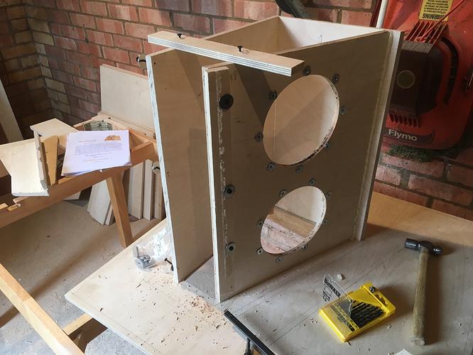
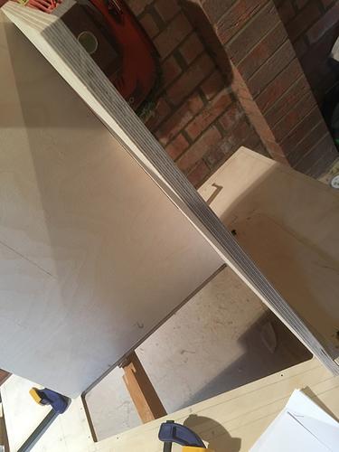
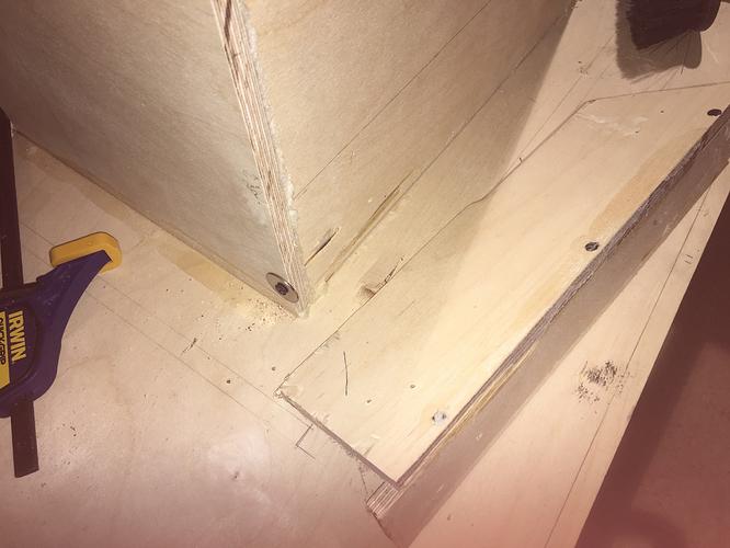
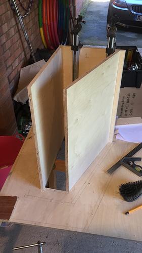
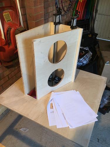
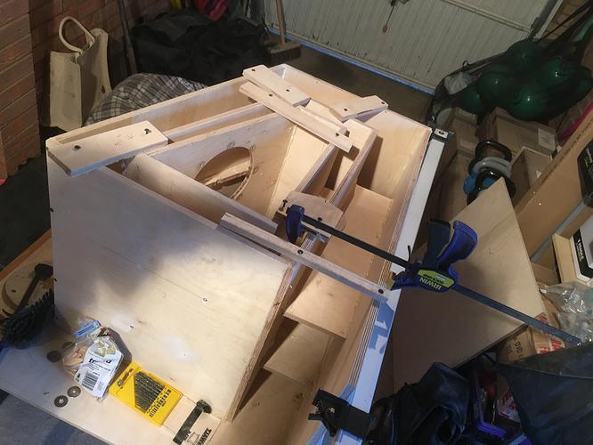
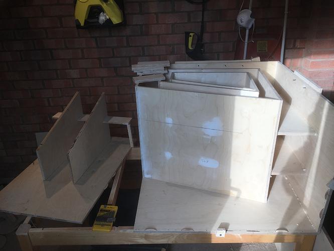
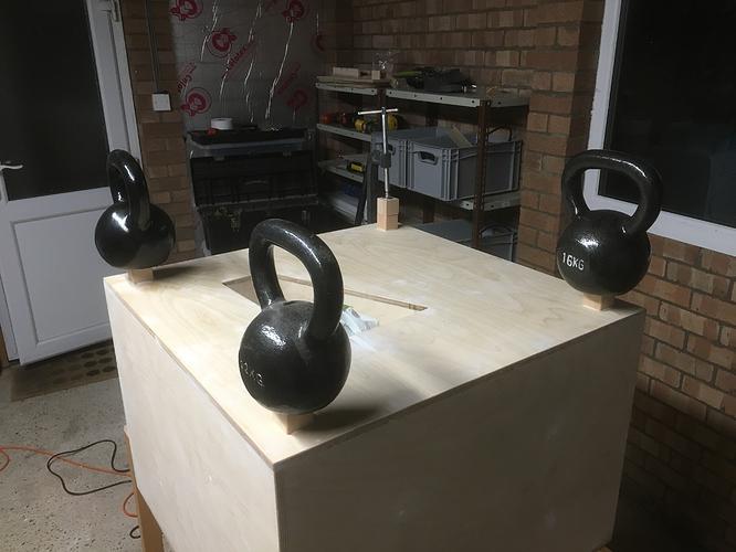
It is critical that panel 4 has to be square, particularly in my case as there was a lot of warp in panel 3. It appears to work, as everything is nice and square now.
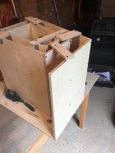
It was starting to look horn shaped!
2 more panels and 4 braces were then installed. I forgot the camera.
Here’s a tip: don’t pay attention to the brace measurements in the plans – they include a “glue safety margin” which means a snug fit is not possible. My advice: fit+square the panel with Jigs/clamps/screws and then measure. After this, slide in until it’s snug, then mark and screw in to the panel. Take panel off, and add glue to the braces. Fit as normal.
Are you going to turn it into an actual table?
Maybe! I’m going to paint it black though – I will consider producing a façade over it.
Testing the drivers and amplifier
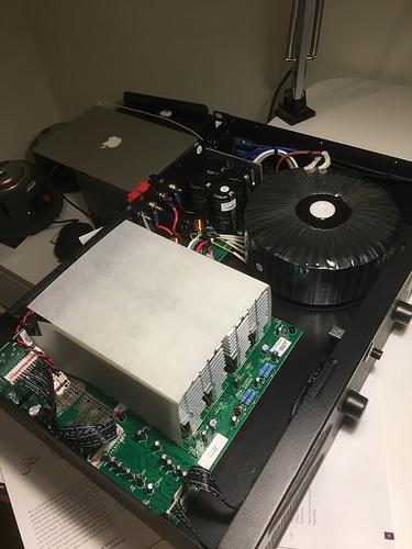
I ordered the first Crown XLi 1500 to drive it. It’s reassuringly heavy and well built. I spy a huge toroidal transformer!
I chose this model (Crown XLi 1500) because:
- Reputable brand
- It’s a PA amplifier and therefore is built to take abuse, unlike a HiFi amplifier.
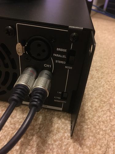
- Selectable input sensitivity for consumer line level (unbalanced, 0.775V) and pro line level (balanced, 1.4V)
- Silly headroom and thus damping ratio (1500 on the front, 450W per channel according to the datasheet, however the mains input says 400W, so I bet the power is really 100-200W RMS per channel, which is still a lot…)
- Thermally controlled fans – be careful, many PA amplifiers are noisy.
It’s silent when under no load.
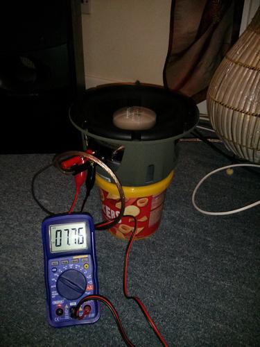
Anyway, it was time for some characterisation before opening it up to learn its secrets.
I played a 1kHz sine wave (play -n synth sin 1000) at probably 90% volume on my Laptop.
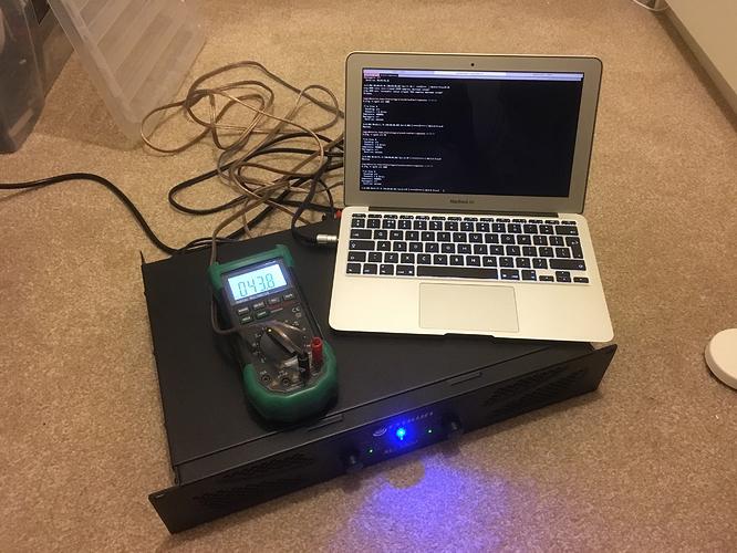
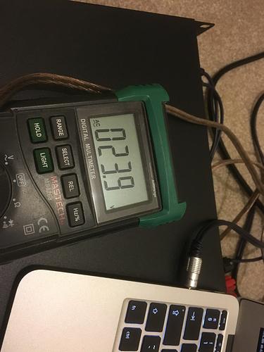
So, approximately 1/2 the voltage and therefore 1/4 the power – a good way of limiting the power if you use consumer line level inputs.
Turning the volume to maximum, it went to 65V (!).
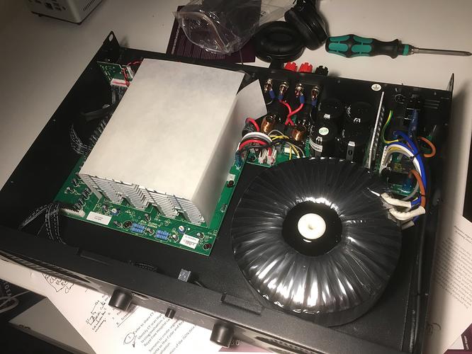
R.M. Caps. Never heard of them. I assume they’re OK, as it’s a Crown.
Knowing the “1500” on the front panel meant nothing, I received clarification of the numbers from Crown after sending an email.
- 400W on the panel is a “regulatory rating registered with a sine wave at 1/8th power”
- The numbers given are “Program” ratings. Normally double RMS as far as I can see. So, 225W per channel. A lot of real power!
I’d assume that the enormous toroid is the thing that makes it heavy.
Yes.
The final pieces
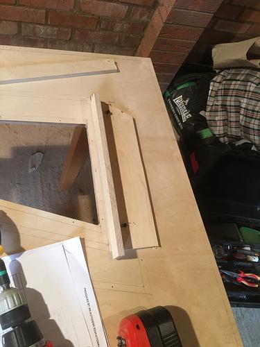
Used a router to trim and some gauge scraps (instead of measuring) to create 2 precise braces for the mouth.
I created dual slots for the support brace with a router, squaring off with a chisel.
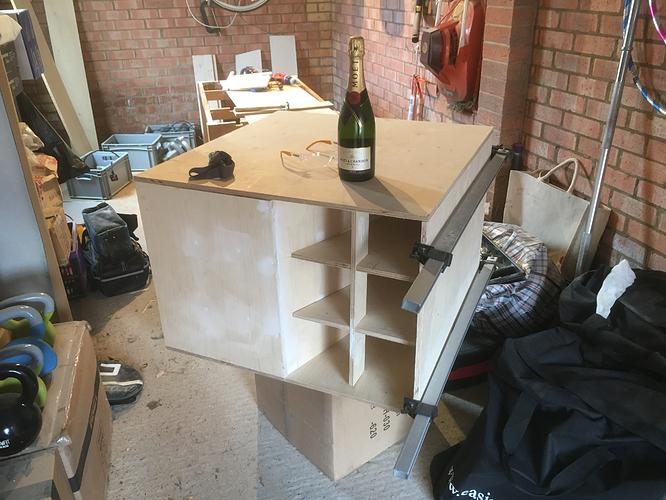
I measured the horn path length – over 4 metres!
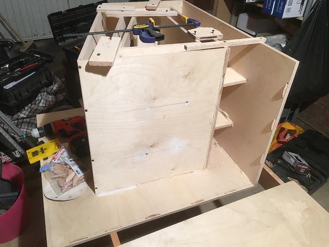
Fitting the last panel and bracing seemed to be the most critical – everything here is visible!
The last panel
All glued in place! Just the side panel remains! This is my favourite shot of the inside:
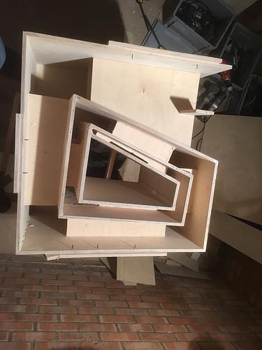
Gluing on the side panel required dozens of screws and some speedy beading of the PU adhesive. It was a race against the clock with my old Black & Decker battery drill.
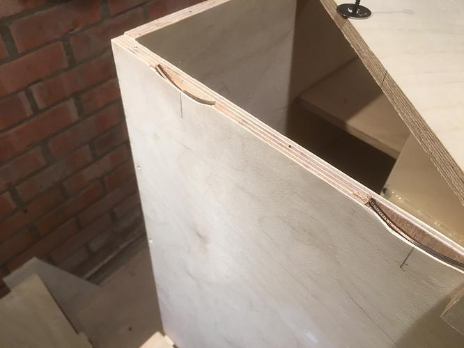
I made a mistake with the biscuit joiner as I was tired that day at 10 p.m. It was nothing some filler won’t fix, mind you:
The side panel was the most stressful part of the build – all 50 screws, 6 jigs, 1 clamp, 14 biscuit joins and about 5 metres of glue.
The first fully assembled test
I hooked up the PA amplifier straight to the laptop, using a software low-pass filter with sox:
play sinc -100
… for a low-pass @ 100Hz, no idea how steep but greater than 6dB per octave.
I also tried some sweeps:
play -n synth 20 sine 100:20
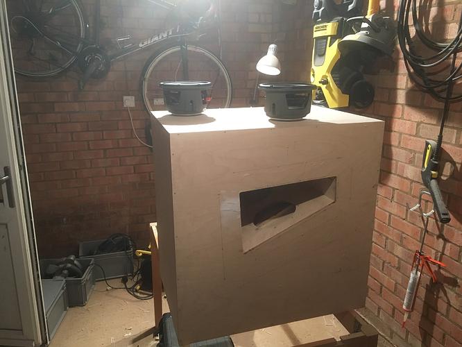
After looking for leaks with silicone pipe as a stethoscope at a low frequency. I’ll be listening for chuffing noises around the gasket of the driver – leaks around the gasket can cause distortion and/or driver damage due to the high pressure.
play -n synth 20 sine 20
Are you going to perform a cat test too?
Yes, later. See the photo.
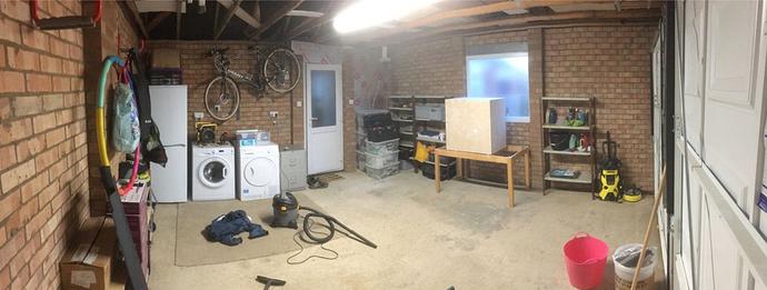
Unfortunately my iPhone crashed so I was unable to take photos of the testing in the garage. I continued the testing with my old HiFi in the lounge.
Test summary:
- The drivers went in smoothly, no problems whatsoever! The Wera mini ratchet was useful.
- Leak testing was interesting and straightforward. I had missed about 5 holes (how?) but at 29Hz they sizzle rather loudly and cause increased excursion and less bass. Plugging them with PU on the fly was simple, I used a bit of aquarium hose like a stethoscope to track down the last one which was tricky to find. The hose was also useful for finding the one leak around the gasket of the nearside driver – it required tightening, that’s all.
- It’s heavy and bulky; somewhat unsurprisingly. 55 kg.
And the bass?
Yes. Yes there is bass. Come and hear feel it for yourself. Hint: vision blurs at less than half volume. Cat is confused.
How many cats can it confuse at once? This is the most important metric.
I’m not sure – my Cat herding skills aren’t what they used to be!
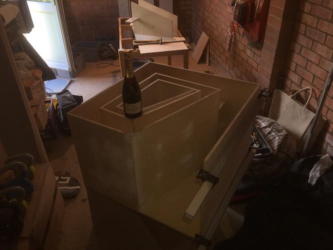
No need, just place some empty boxes in the vicinity of the sub, wait, then harvest the cats.
The subwoofer kind-of resembles a box…
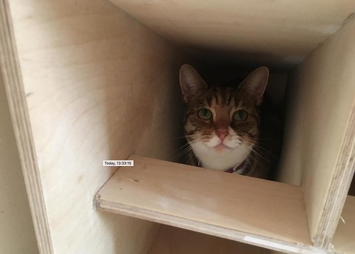
It didn’t take long. I don’t think I’ll need any boxes!
Slowly increase the volume of ‘woofer cooker’ and determine the maximum volume your cat can
endurewithstandsurvivetolerate.
I was asked if there was bass. This video should answer that question: https://www.youtube.com/watch?v=2yWKUfmBg20
The sub is 6 meters away in the lounge.
This appears to confirm there is at least some bass. Approved.
We realised the subwoofer weighs exactly as much as my brother’s girlfriend. It’s 1.00 Katies!
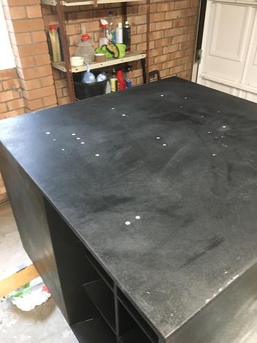
I started to sand/fill/machine it now. I still need to add the removable side panel and paint it, but after moving house. I put the project on hold for a few weeks whilst we moved.
Measurement tools
We successfully moved house, for the second time during this long-run-on project! The subwoofer only took a few knocks on the edges, so I’m glad I decided not to machine the edges before moving else the damage would be more than superficial.
In the meantime, I ordered some “Tuffcab” paint + rollers to give a tough, textured effect. I also got an omnidirectional measurement mic soon for use with Room EQ wizard.
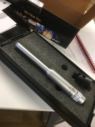
The calibrated measurement mic. I would be using this with Room EQ Wizard and baudline to characterise the sub.
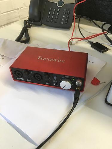
The Focusrite Scarlett 2i2 arrived, which I used to interface with the mic. Currently in use as a headphone amp.
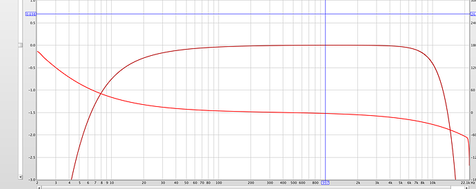
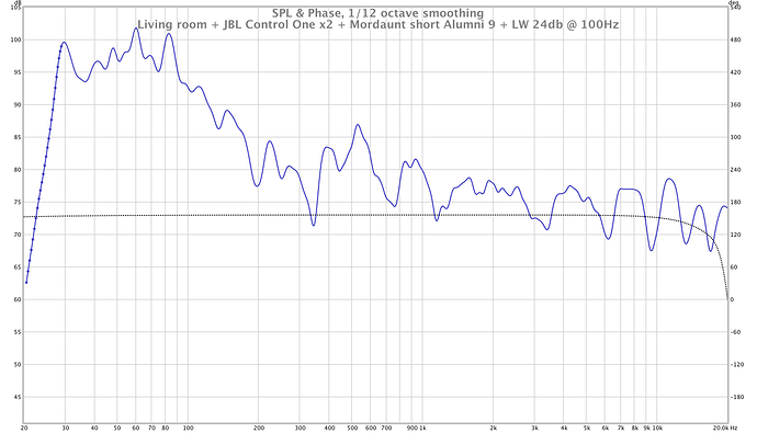
As you can see, the bass gain is higher than the mains. It’s my “house curve” – apparently technically flat is a different thing to perceptually flat.
To be honest, I was expecting a significant dip at around 100Hz LW crossover point as it also happens to be the -3dB roll-off point of the mains. It seems to be lost in the natural variation!
Finishing the cabinet
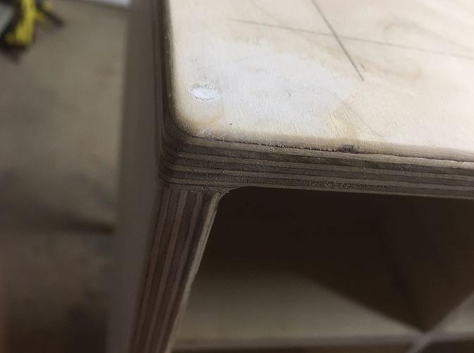
I started by routing the edges with a 1/4" roundover bit:
In other subwoofer related news, I decided not to put a side cover on. Adding a side cover would improve the appearance at the expense of some bass which is unacceptable!
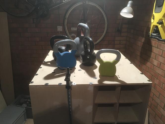
Instead, if you don’t have a side panel you need to install the speaker with the speaker hole 38 to 50 mm to a boundary such as a wall or floor; which is why I’ve decided to make this a short/wide speaker instead, and install 40mm feet. Of course, it can still be used in a tall configuration if you stand it on its side, in which case the feet work as a gauge for the wall distance.
I used 40mm hardwood blocks from eBay and routed the exposed edges after a lot of rationalisation involving surprisingly expensive sofa feet.
I glued the feet for optimum strength as I was limited as to what fasteners I could use given appearance and location.
Used on its side near a wall, the raised height should preserve the tuning so there isn’t a dip at 80Hz.
The first coat of watered down paint!
The filler (generic “No Nonsense” filler) created a problem – the paint bumped up where the filler was used (definitely nonsense) which meant I had to sand the first layer which was a 50/50 water + paint mix. Next time I shall use wood filler.
The second coat (top only) is a dramatic improvement.
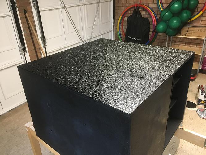
Finally, 2.5 coats on all sides and I still have 30% of the paint left. I may add another layer for no reason later this week.
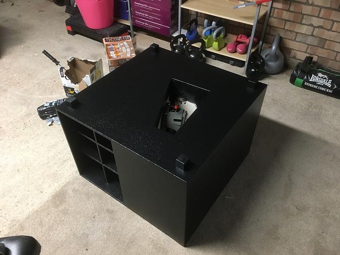
There is an awesome floating effect due to the feet. I’ll show that when room testing begins tomorrow!
Thoughts after 2 years of using the subwoofer:
- I’d consider a bass-reflex design next time. I don’t care about efficiency as much as I do size.
- I really shouldn’t have used multi-purpose filler for the wood as it expanded leaving bumps in the wood. I should have used wood filler, as expected…
- I still love the subwoofer and it has never failed to produce alarming levels of bass, and provide sensible bass extension the rest of the time
- The cat loves sitting inside the subwoofer… when it’s off!
Thanks for reading! If you enjoyed this article or have comments, please consider sharing it on Hacker news, Twitter, Hackaday, Lobste.rs, Reddit and/or LinkedIn.
You can email me with any corrections or feedback.
Tags:
Related:

