
3D printed wall mounted touchscreen panels from cheap tablets
For my home-automation project I needed some professional-looking touchscreen panels capable of running the web-based interface that I developed to control my home.
Looking around, I concluded that I’d have to make the panels myself given the proprietary nature and expense of existing home automation control panels. The real challenge here is to make the panels look professional.
For the first prototype I tried the official Pi industrial LCD with a Pi 2.0. I mounted it to a project box, which would fit inside the wall. This seemed to work OK, and indeed it was possible to run a web browser (epiphany, I think, or Chromium) but the downside was the limited resolution of the screen; the cost was acceptable and the Pi platform is relatively open. Mounting and assembly required a fair amount of effort.
The Pi Prototype
For the next prototype, I considered using an Android tablet. I know that it’s possible to run an “immersive mode” full screen web view that stops the display from sleeping, plus most tablets have a decent display with the bonus of an integrated battery backup. The downside was that there was no suitable way of wall mounting a tablet. There were several “kiosk” type options, but these were limited (mostly) to iPads, were expensive, and most had cumbersome swivel mounts attached. Other than this, eBay revealed acrylic wall mounts for various tablets — but I quickly dismissed them as there was no routing for the power cable and they looked tacky.
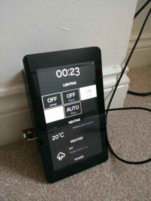
The next day, Amazon happened to have a really good deal on the 5th-gen Fire Tablet – at £35 I bought 2 in the hope that they’d be suitable. I was lucky.
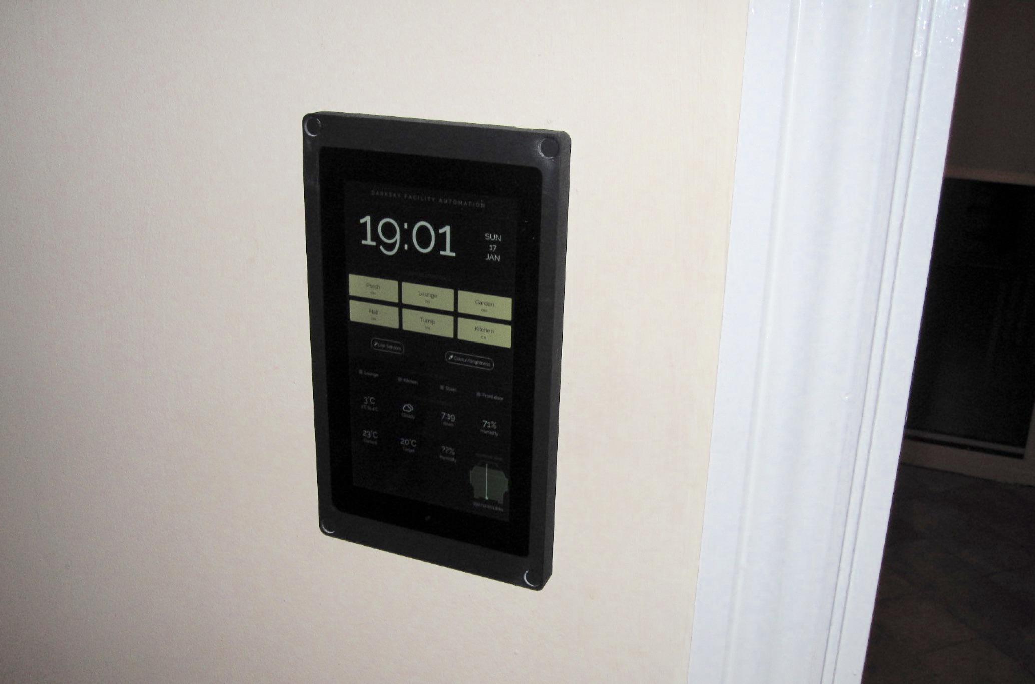
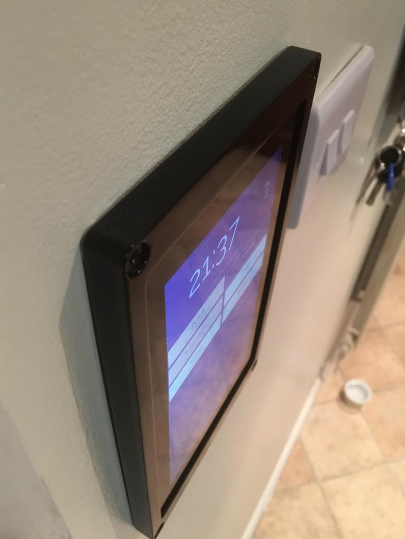
A sneak peak at the result, in situ:
Having chosen the tablet, I decided that I needed to fabricate my own bezels which would mount flat to the wall, hide the power cable and tablet-like appearance. I wanted the design to be manufacturable via an additive or subtractive process so it could be 3D printed or milled.
For this project I wanted to use an Open-source toolchain which led me to OpenSCAD, FreeCAD and BRL-CAD. OpenSCAD is a Constructive Solid Geometry based CAD tool with its own [DSL] that allows for a purely programmatic (thus intrinsically parametric) approach to 3D design. FreeCAD is a more traditional parametric CAD package analogous to the more fully featured commercial counterpart, AutoCAD.
I picked OpenSCAD (as the programmatic approach interested me) which resulted in the following chain:
.scad OpenSCAD DSL file -> .stl STereoLithography surface geometry -> Slicer -> .nc G-Code -> 3D printer
I don’t have a 3D printer so I had to find a shop to print the design for me. Looking around, most places support the FSM or SLS based 3D printing method. Looking around, prices varied from around £40 to £180 (!) for most 3D-print shops, to over £800 for a print from a “rapid prototyping” shop.
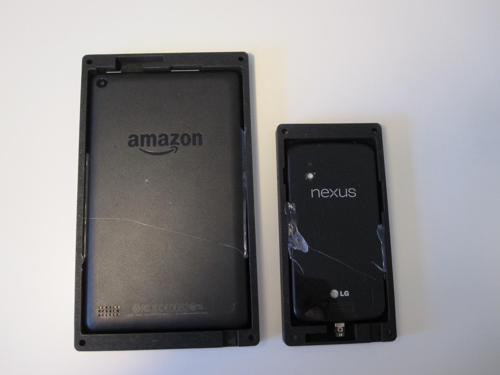
I ended up going with 3D print UK1 who charge by enclosed volume rather than area; because of this I also made a smaller bezel for my old Google Nexus 4. They also offer a black-dye option, which I went for.
Anyway, here’s the design, bezel.scad. Unfortunately, making fillets is a lot of effort2 in OpenSCAD. Round-overs are easier but require a bit of work so I decided to use scad-utils for its morphology module, which can round arbitrary 2D shapes but can be slow.
// Unit: Millimetres, implicit.
// https://github.com/OskarLinde/scad-utils/blob/master/morphology.scad
// empty in /Users/<username>/Documents/OpenSCAD/libraries
use <morphology.scad>
Don’t forget to increase the number of faces for a smoother corner!
$fn = 80;
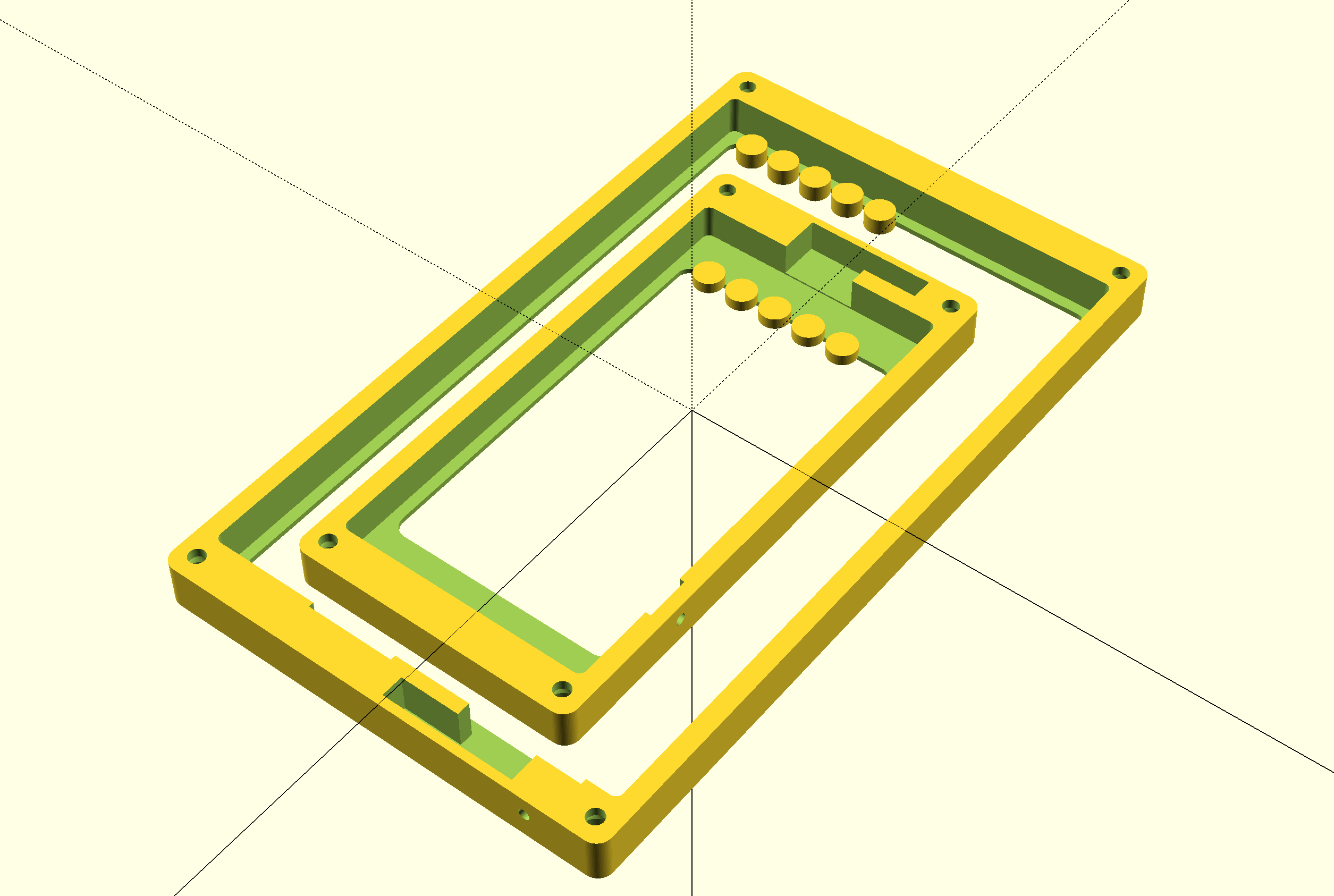
I started with a basic cuboid larger than the tablet, subtracting a tablet-sized cuboid from it, and finally removing a window from the remainder. I defined this shape as a module such that it can be used for any tablet size.
// basic portrait bezel
module bezel(x,y,z,overhang=[3,3,3,3],front=2,top=10,bottom=10,sides=5) {
    // overhang: top, right, bottom, left (like CSS)

    difference() {
        // 2D shape is extruded (instead of 3d to begin with) such that morphology library can be used

        // bounding box
        linear_extrude(height=z+front) rounding(r=4) square([x+2*sides,y+top+bottom]);
        // tablet cut out
        linear_extrude(height=z) rounding(r=2)  translate ([sides,bottom,0]) square([x,y]);
        ///translate ([sides,bottom,0]) cube([x,y,z]);
        // display cut out leaving a frame
        linear_extrude(height=z+front) rounding(r=4)  translate ([sides+overhang[3],bottom+overhang[2],0]) square([x-overhang[1]-overhang[3],y-overhang[0]-overhang[2]]) ;
    }


}
Next, I needed to create mounting holes. Pan-head screws with an oversize hole would allow for some mounting error, but countersunk screw-heads would result in the best finish. I could mount them:
- Flush with the front
- Sunk with a plug
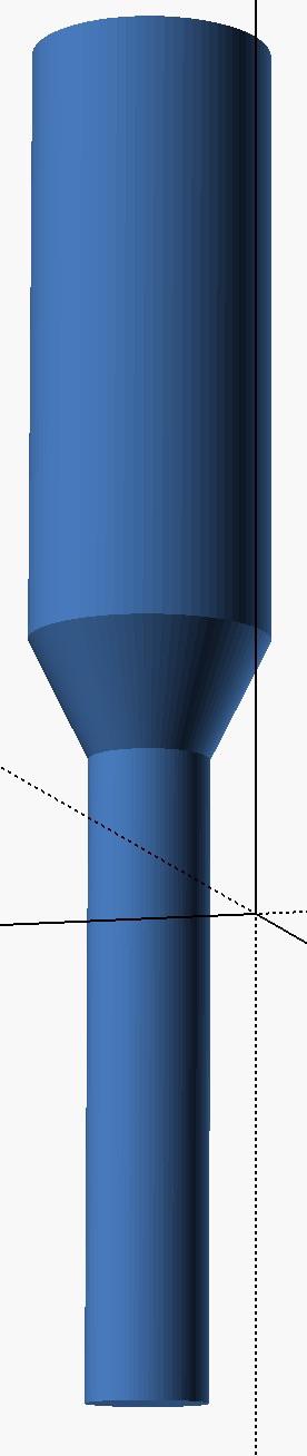
I went for option (2) and then revised to option (1) when I got the first print. Here is the shape, set for a 4mm woodscrew will plasterboard wall-plugs from Screwfix:
This is also a parametrisable module:
module countersunk_screwhole(head=8,diameter=4,height=25) {
    // expand 10% for some play
    scale([1.1,1.1,1.1]) {
        // head
        translate([0,0,-diameter/2]) cylinder(h=4,r1=diameter/2,r2=head/2,center=true);
        // shank
        translate([0,0,-height/2]) cylinder(h=height,r1=diameter/2,r2=diameter/2,center=true);
        // plug hole
        translate([0,0,10]) cylinder(h=20,r=head/2,center=true);
    }
}
Protip: if you don’t want z-fighting,3 make sure you extend the subtracted volume beyond the boundaries. Z-fighting is only an issue with the quick preview render. Here it is:
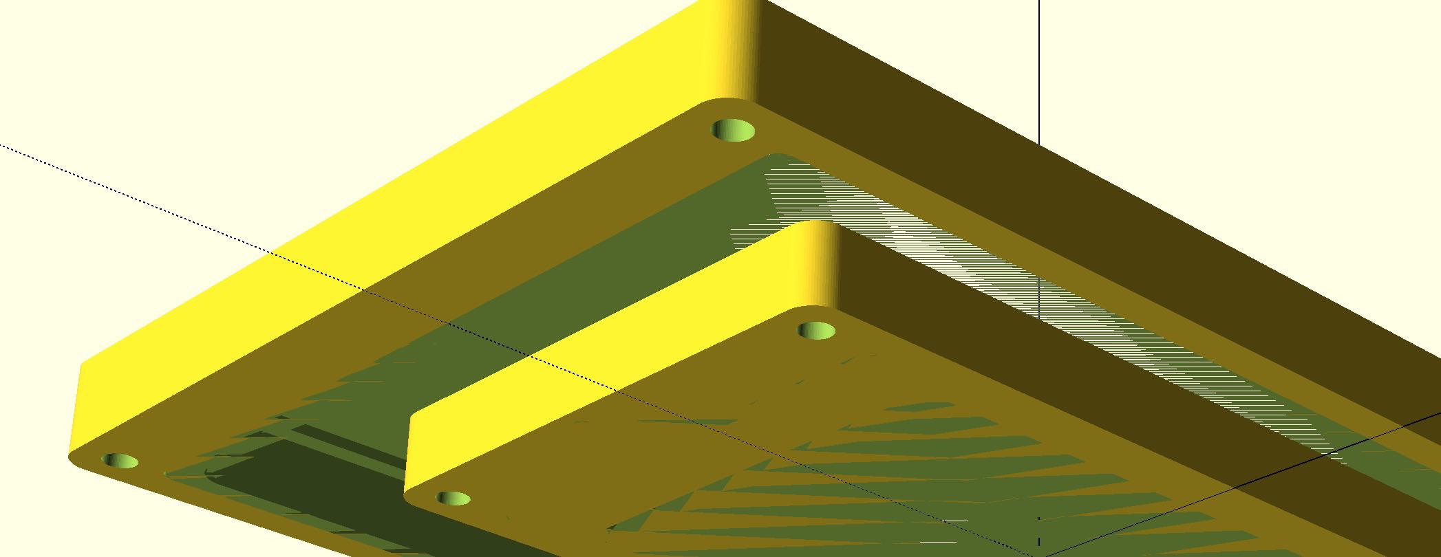
Next, I combined the screw cut-outs with the bezel.
module mountable_bezel(x,y,z,overhang=[3,3,3,3],front=2,top=11,bottom=11,sides=5) {
    height = y + top + bottom;
    width = x+2*sides;
    screw_z = z+front-1;

    difference() {
        bezel(x,y,z,overhang,front,top,bottom,sides);
        translate([5.5,5.5,screw_z]) countersunk_screwhole(); // BL
        translate([width-5.5,5.5,screw_z]) countersunk_screwhole(); // BR
        translate([5.5,height-5.5,screw_z]) countersunk_screwhole(); // TL
        translate([width-5.5,height-5.5,screw_z]) countersunk_screwhole(); // TR
    }
}
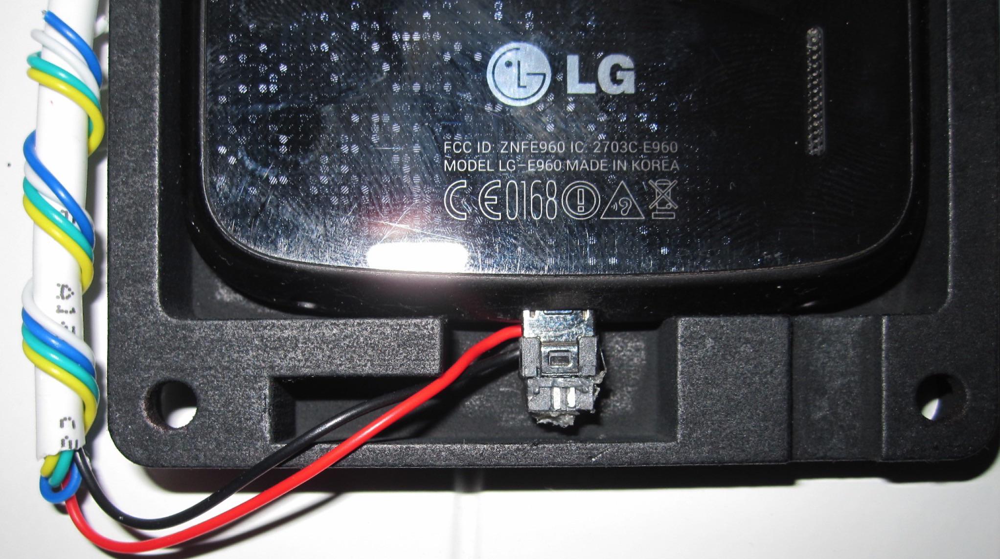
Almost there! Next I added a few cut-outs for buttons specific to a Fire tablet, and a small (10mm) area for a low-profile solderable micro-USB connector from eBay; having a full-sized micro-USB connector connected would spoil the look. I didn’t forget a hole to actuate the power button with a toothpick for when the tablet decides to crash – just an assumption that hasn’t happened yet.
module fire5_bezel() {
    difference() {
        mountable_bezel(115,191,10.6,front=1.5,top=12,bottom=11);

        // volume rocker (30-54)
        translate([30+5,10+192,0]) cube([24,1.8,10.8]);

        // microUSB solder connector + wire routing (25 45)
        translate([2*5+115-45,10+191,0]) cube([20,11,10.8]);

        // power button cutout
        translate([2*5+115-27,10+192,0]) cube([14,2,10.8]);

        // power button hole
        translate([2*5+115-20,10+191,10.6/2]) rotate([270,0,0]) cylinder(h=20,r=1.5);
    }
}
The final design
…fast forward a week or so, and some exciting parcels came so I tacked in the tablet/smartphone with some hot glue.
Using 6-core alarm cable routed to a fused @ 1A 5V power supply though the wall, I soldered on the low profile connectors:
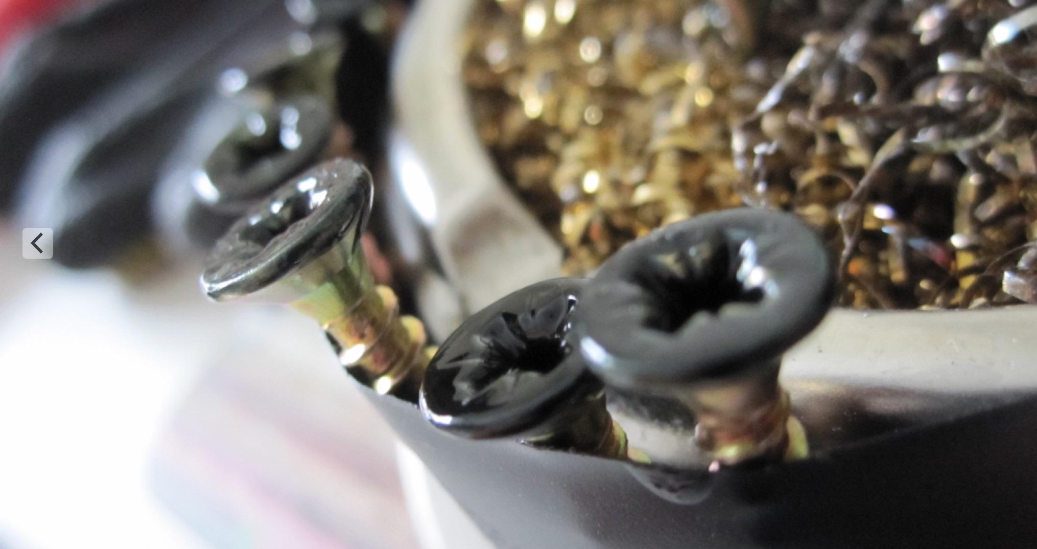
The screw plugs proved annoying and irregular so I decided to paint the screws instead, using some black nail polish:
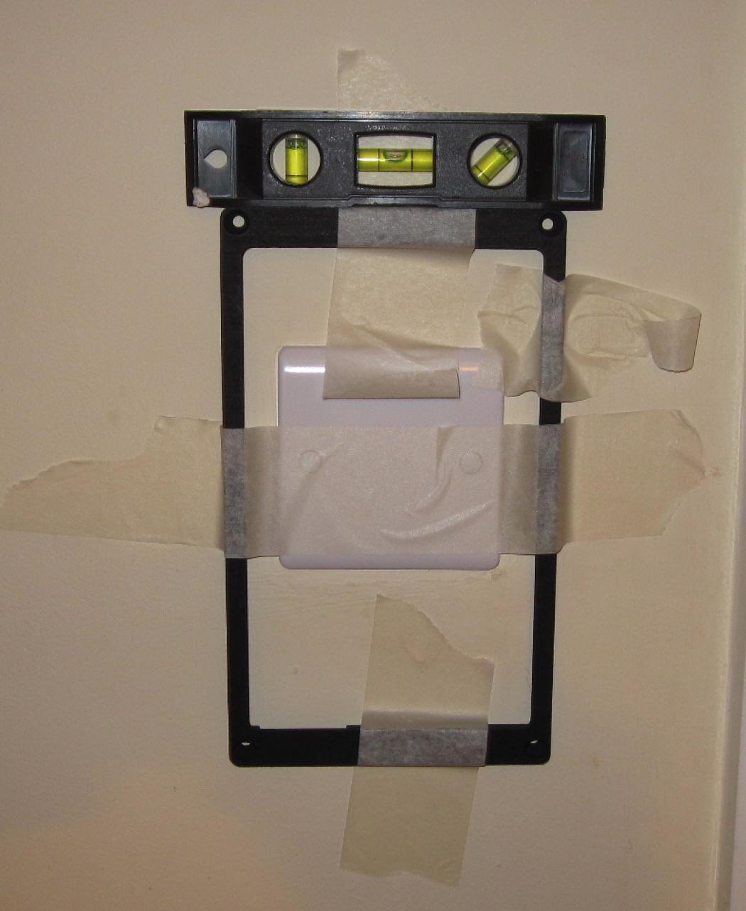
There is a bit of a knack to mounting, which is a low-tolerance operation:
- Tack the frame to the wall with masking tape and level it off
- Drill 4mm pilot holes through the bezel holes
- Remove the Bezel
- Ream out the holes with a 6mm drill bit
- Insert 6mm wall plugs with a mallet
If you want to be really clever, providing you’re careful and “consult the nearest qualified electrician” you can install around an existing (and as a consequence, redundant) light switch! Avoid the wires, and you can remove the switch plate. In my case, the original switches have been hard-wired as I’ve installed Philips Hue bulbs all over the bottom floor with custom software to control them – more on that later.
As for the UI you see in the panel, it’s powered by ReactJS + MQTT. I’ll post about that soon. If you use this design in your project, please attribute this website and I.
Update: I spray painted them:
2019 update: I re-wrote the design and released the code on github. Here’s the blog post about it. I also have a 3D printer now, so was able to iterate a lot for an improved product.
Thanks for reading! If you enjoyed this article or have comments, please consider sharing it on Hacker news, Twitter, Hackaday, Lobste.rs, Reddit and/or LinkedIn.
You can email me with any corrections or feedback.
Tags:
Related:

