
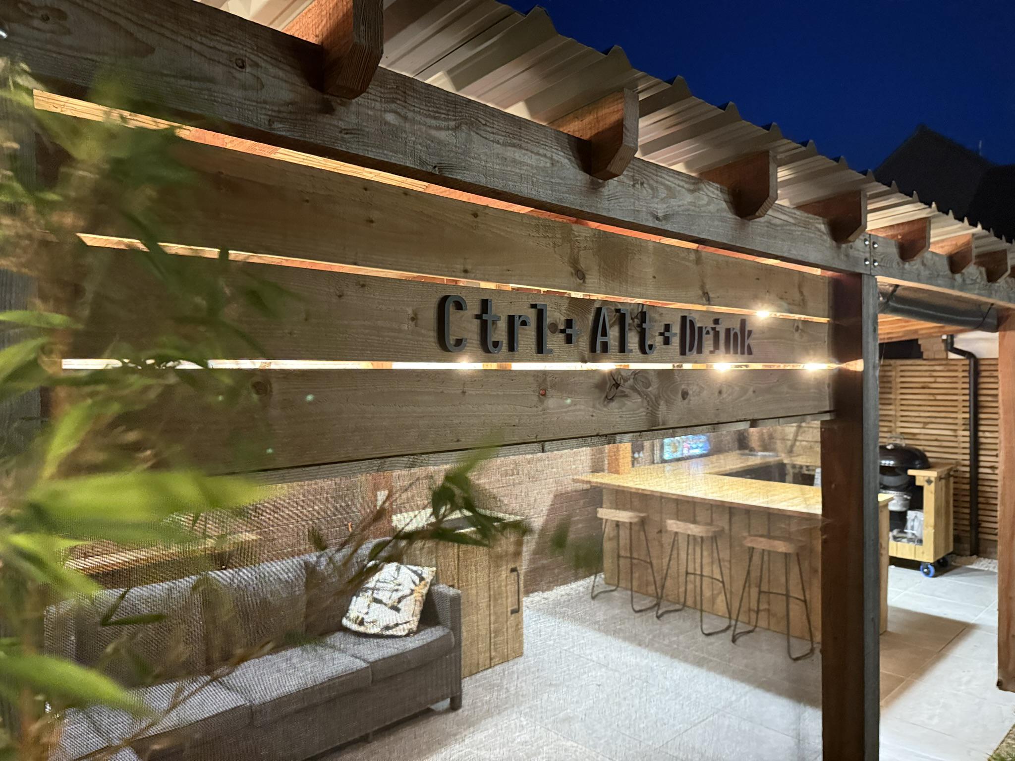
Ctrl+Alt+Drink: Adventures building a garden bar
Yep, that’s me dressed as Jaws1 from Moonraker. We had a 007 themed opening party because everyone kept saying the motorised drinks cabinet looked like something from a Bond film.
I turned the back of our garden into a bar, complete with a motorised hidden drinks cabinet, DIY automation, and plenty of lessons learned along the way.
I’ve never blogged about the DIY projects I do at home, despite spending a lot of my time on DIY. However, I think this project has reached the threshold of being interesting enough to write about. I hope this post is useful to you if you’re thinking of building a bar or similar outdoor area.
I’ve built the bar over the last 3 years; I’ve designed it for BBQs and parties, as well as a practical place for working from home. The larger parts were made with help from my Dad and my Brother.
I’m biting through some steel gondola wire, in case you were wondering. ↩︎
Motorised drinks cabinet
2023
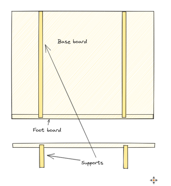
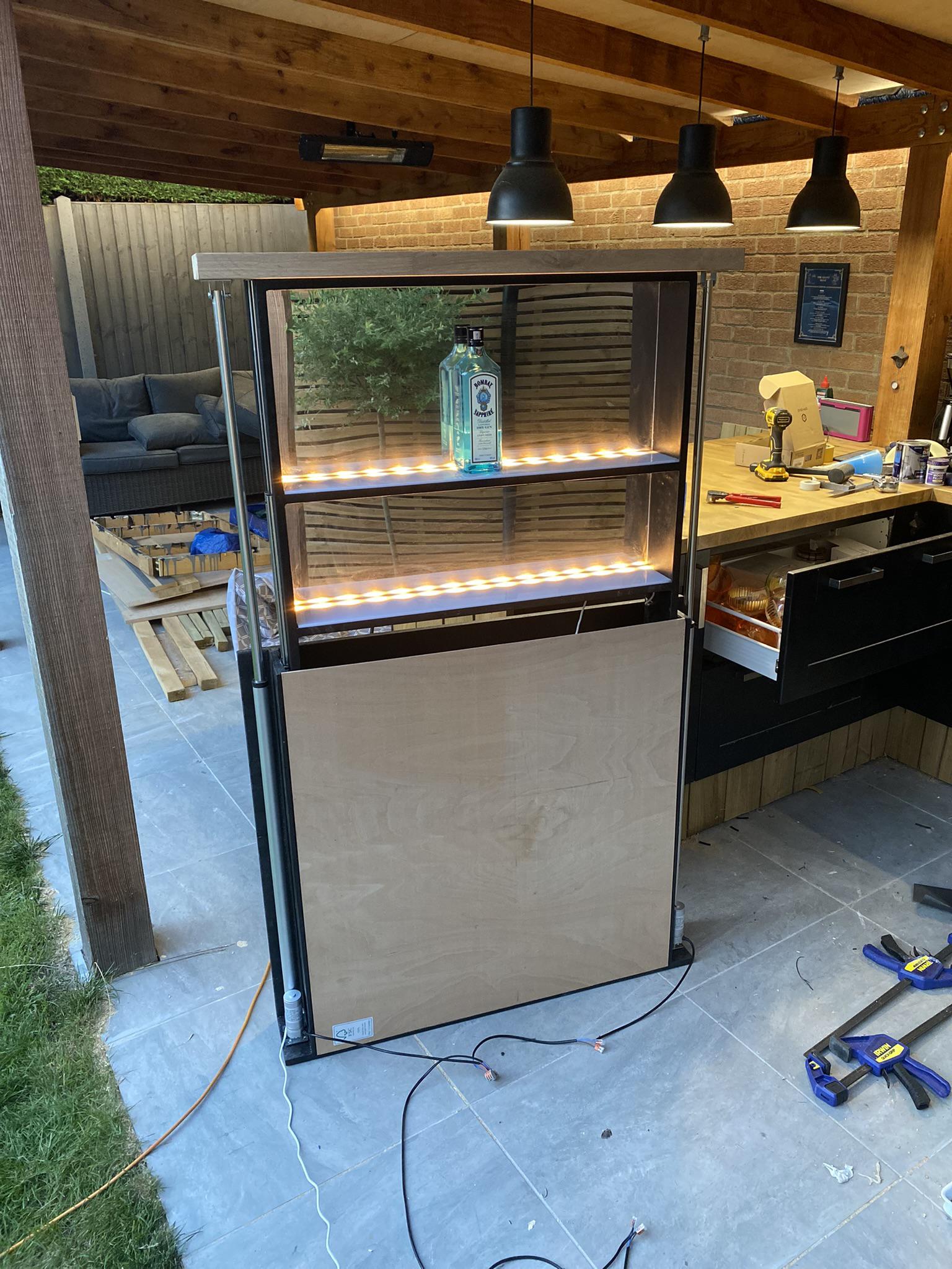
I wanted a neat way of storing spirits without exposing them to sunlight or dust. Of course, I could have built a cupboard, but I wanted something a bit more fun.
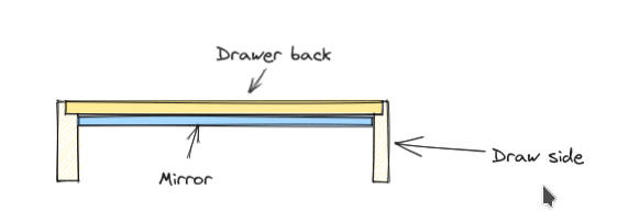
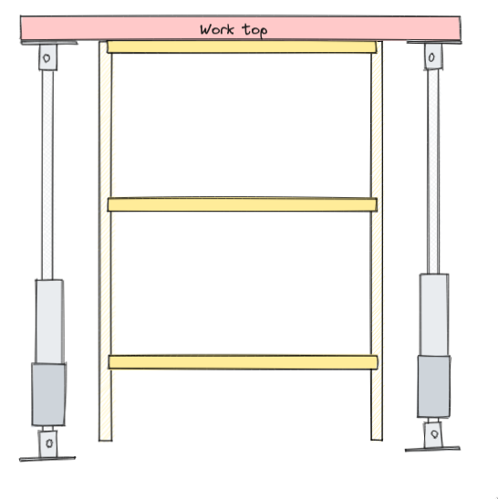
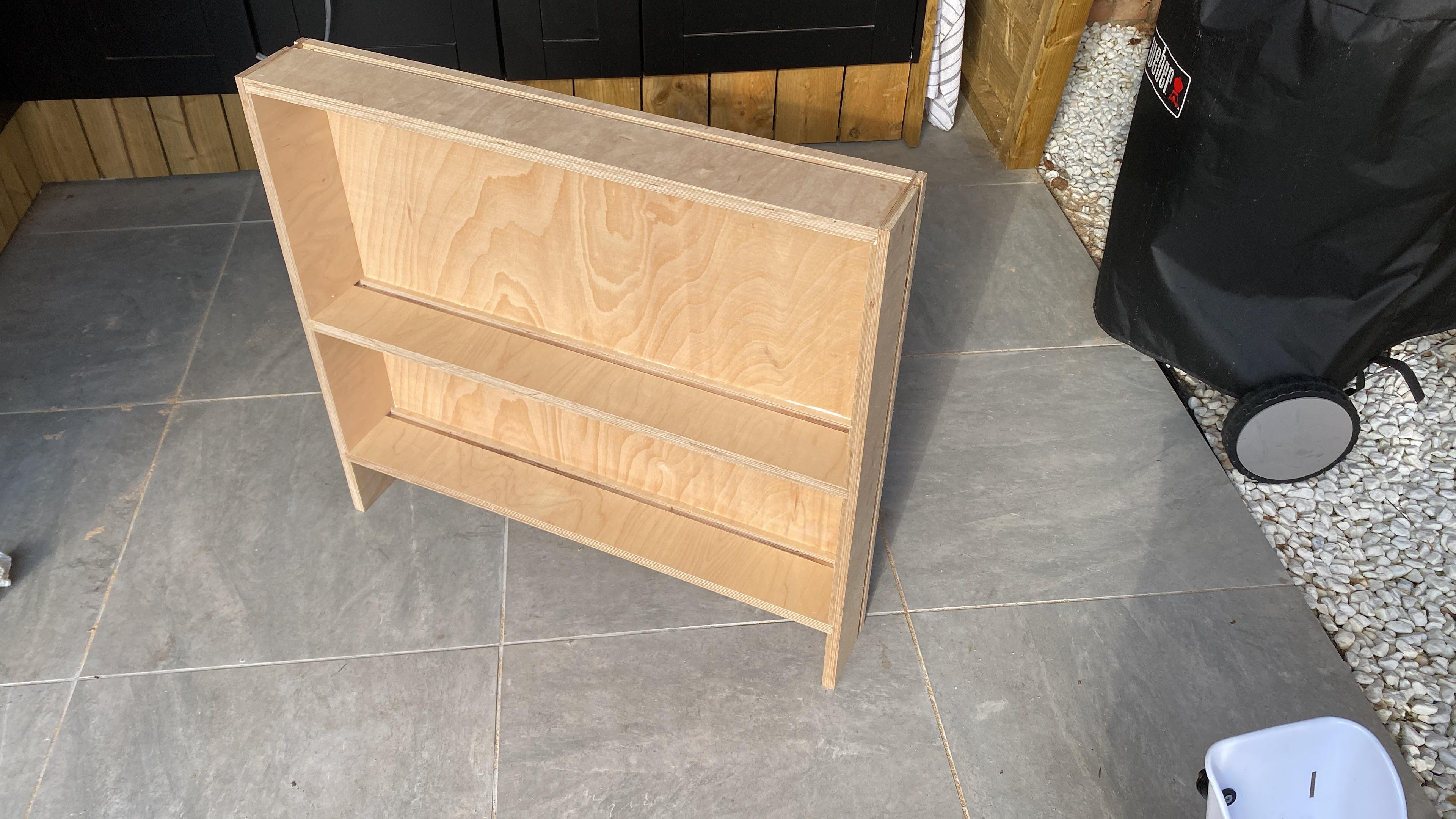
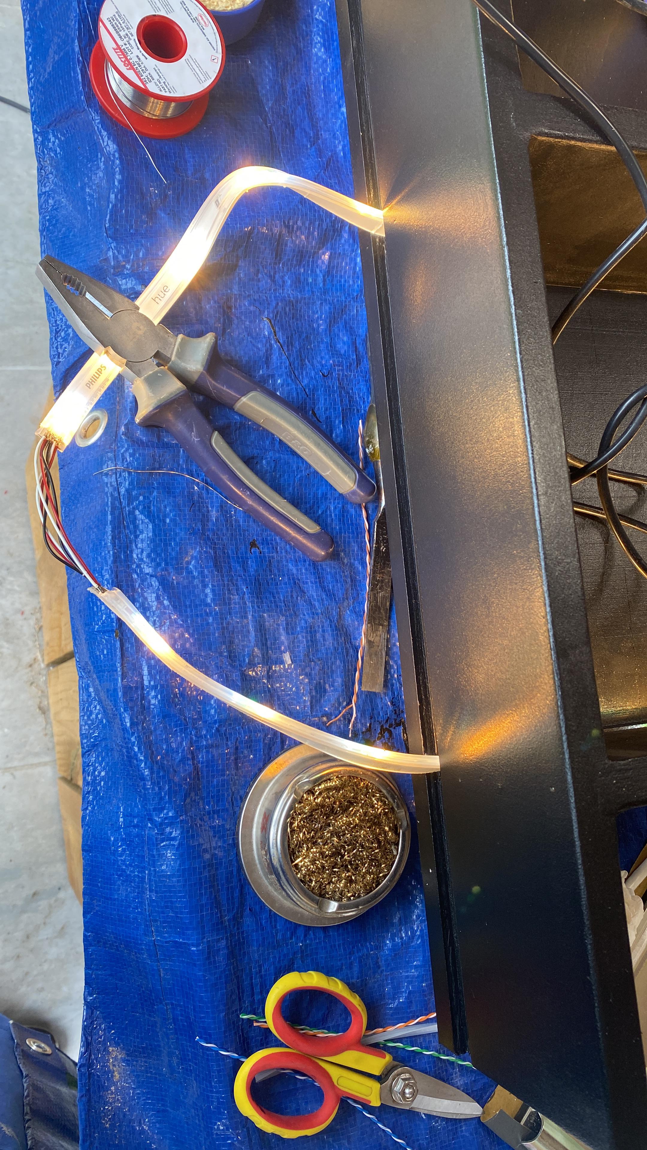
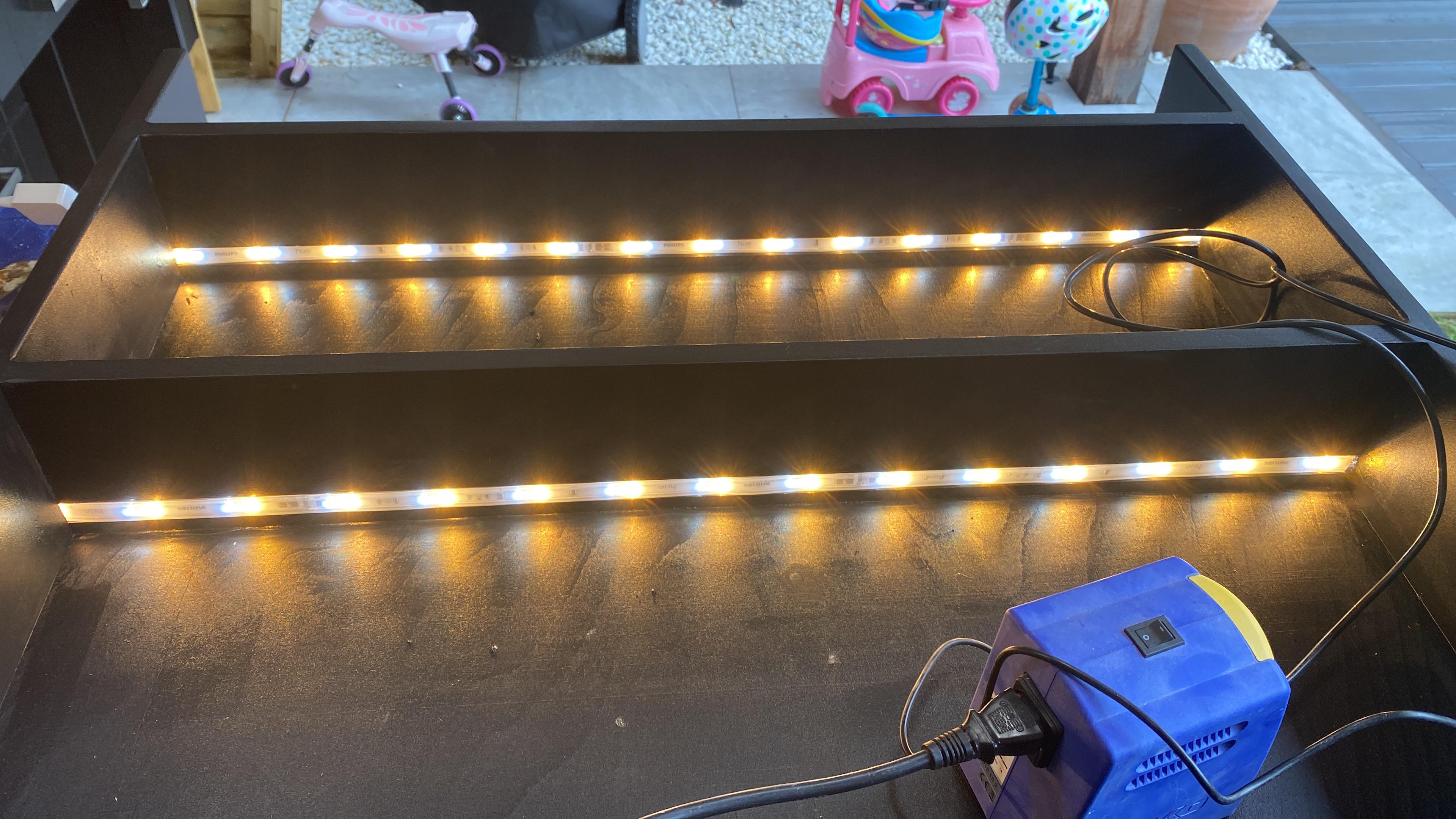
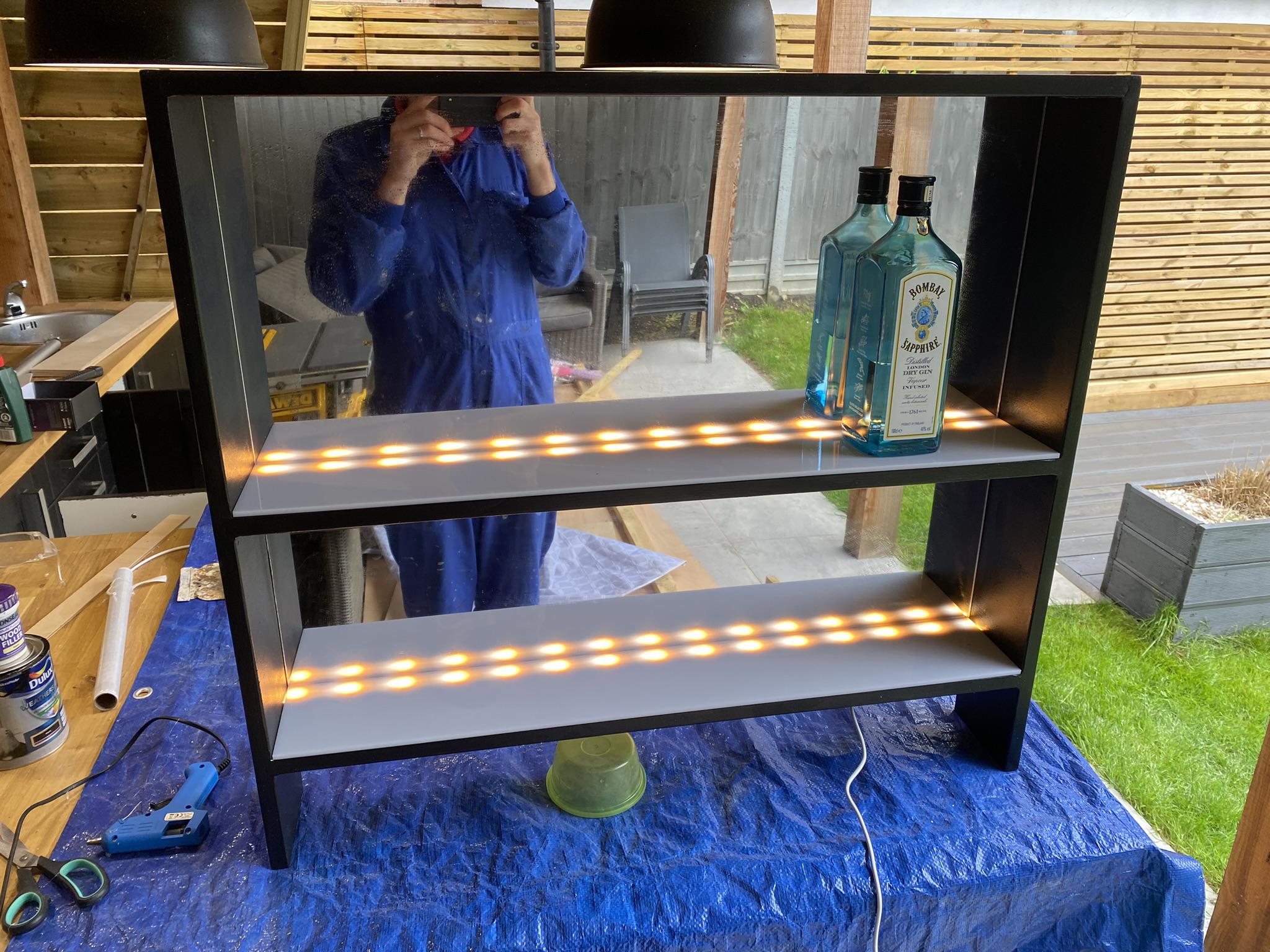
My idea was to build a cabinet that is essentially an upwards-facing drawer with 2 electrical linear actuators that would raise and lower the drawer on demand. I figured I may as well line the drawer with LEDs and a mirror to enhance the effect.
To design it I sketched it first on excalidraw. I had considered modelling it in OpenSCAD, but given it’s not possible to measure things or produce technical drawings.2 I had used OpenSCAD before for a manual speaker design – by separately calculating and echoing the measurements in the console. This can introduce errors.
Given I didn’t want to learn FreeCAD or tolerate Fusion 360, I used a spreadsheet to figure out the measurements. As it turns out there are dozens.
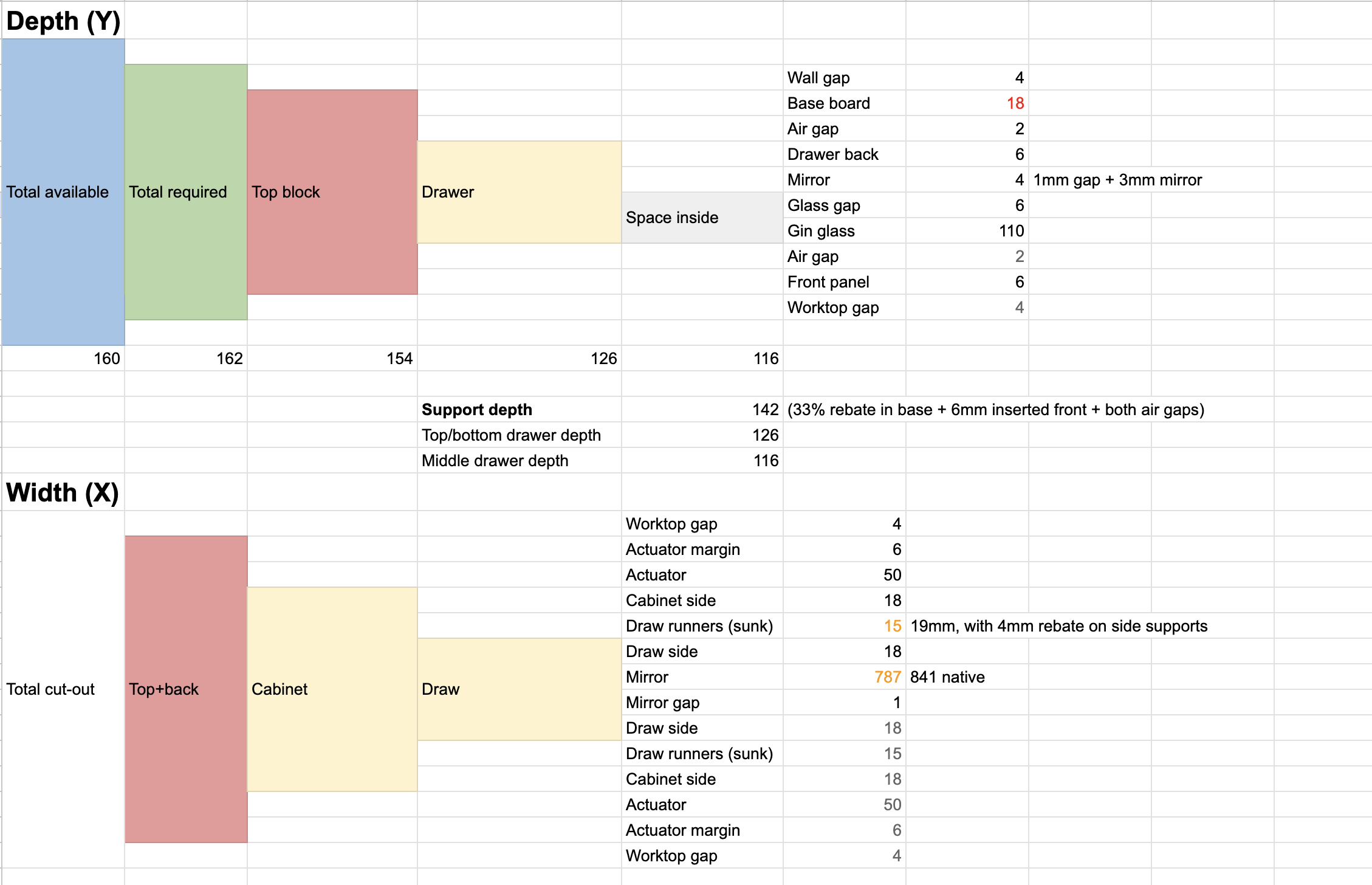
Here’s the spreadsheet I used to calculate the measurements, in case you want to replicate. I don’t recommend it; it’s best to use CAD.

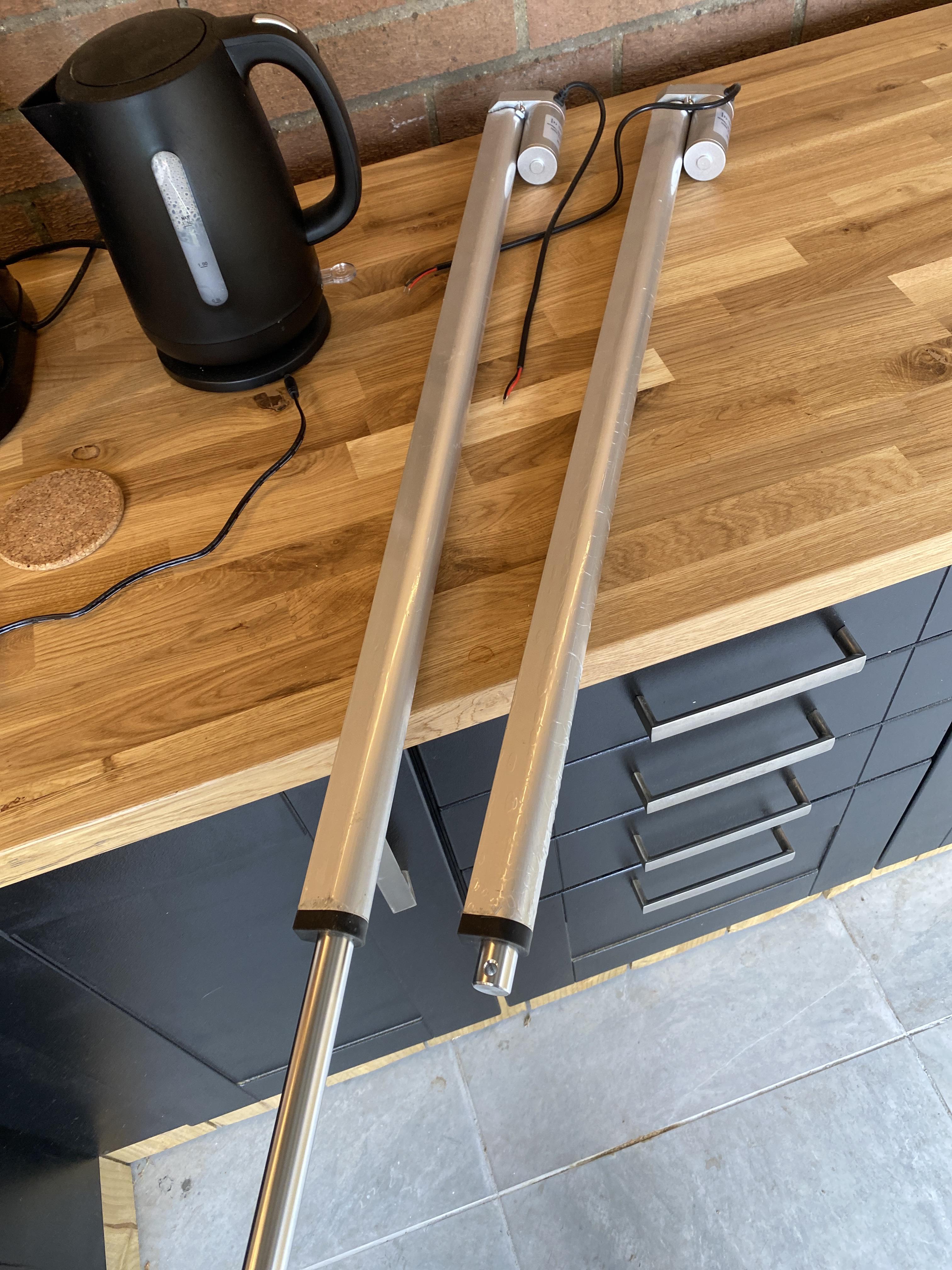
A friend gave me the idea to use electric linear actuators – they were readily available and inexpensive on eBay. I got the fastest ones I could find – 600mm/s and rated for only 20KG each (faster is weaker) at 12v.
I borrowed a friend’s table saw to cut the plywood to size – while I could have used my circular saw, the table saw made it far quicker and easier. It also meant that I could create rebates fairly easily, which probably helped with the rigidity of the design; important as there are 2 possibly unbalanced linear actuators.
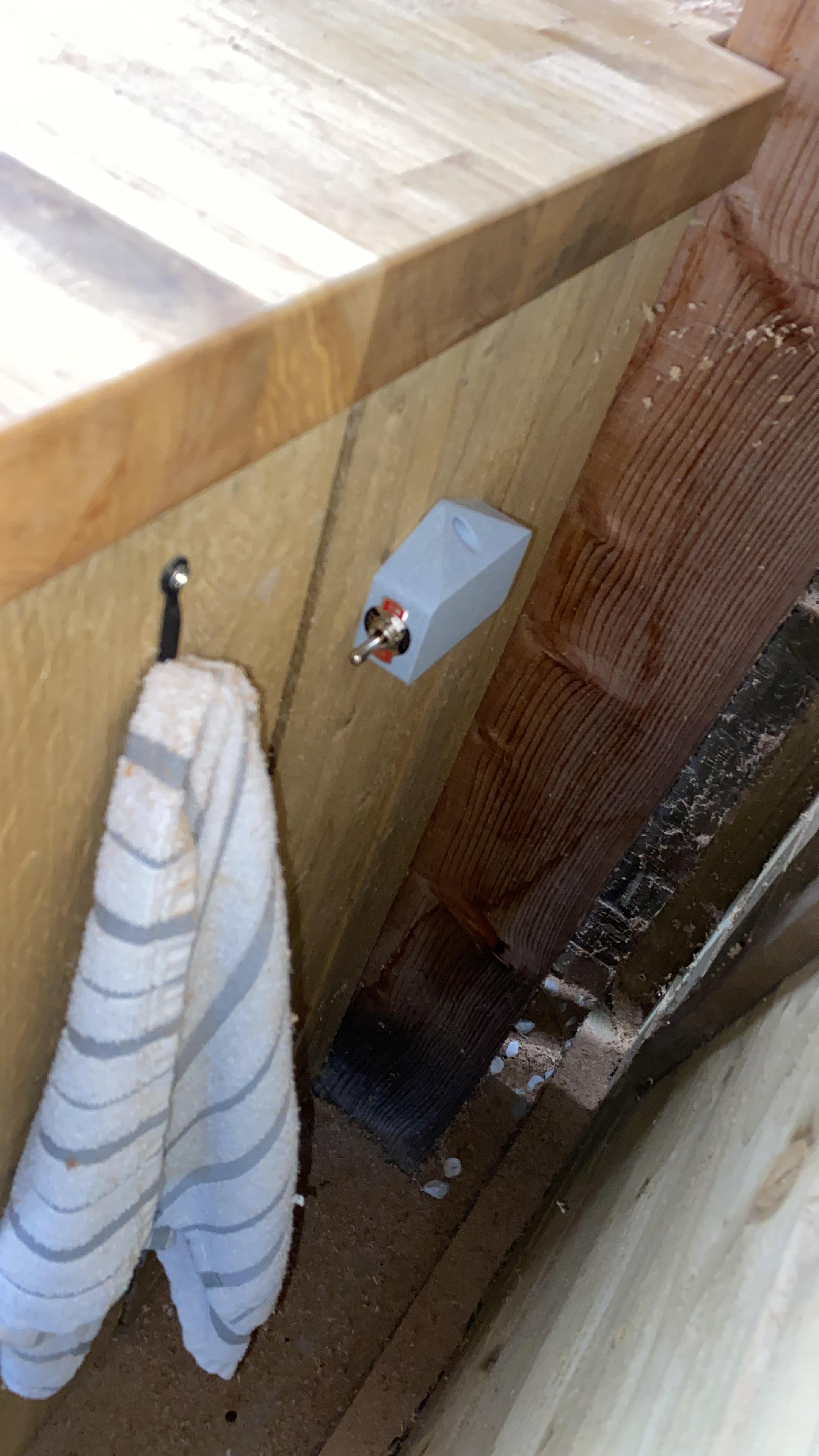
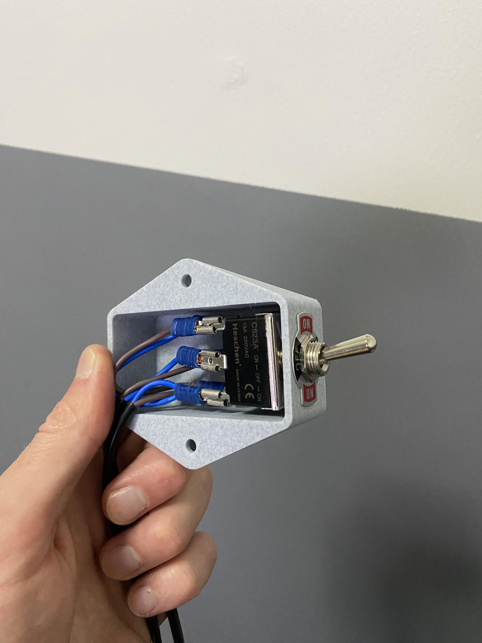
As for wiring, the linear actuators already had limit switches built in so all I needed to do was wire up a DPDT toggle switch to reverse the polarity. This way the switch controls up/down and as I chose a 3-position switch, it can also stop.
I glued the plywood with PVA, held in place with brad nails and sometimes clamps.
When testing the actuators, it was clear they moved at different rates – this meant the cabinet would warp a bit, and go up at an angle. Not ideal. I experimented with adding some low-resistance power resistors in an attempt to balance the actuators – this temporarily worked, but quickly went wrong again.
In the end, the actuators simply needed to be worked in. After about a dozen cycles, they were good to go and exactly matched in speed.
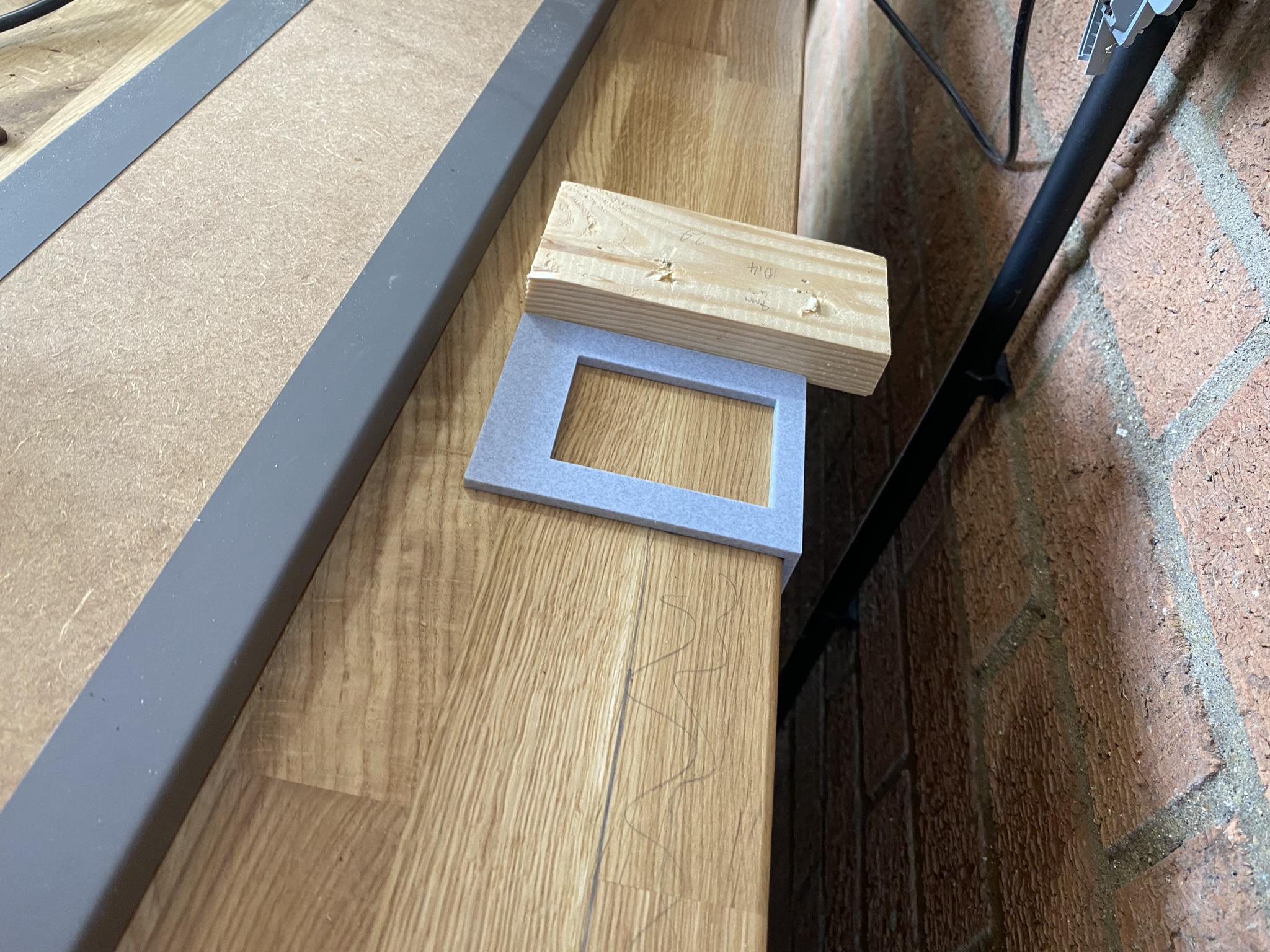
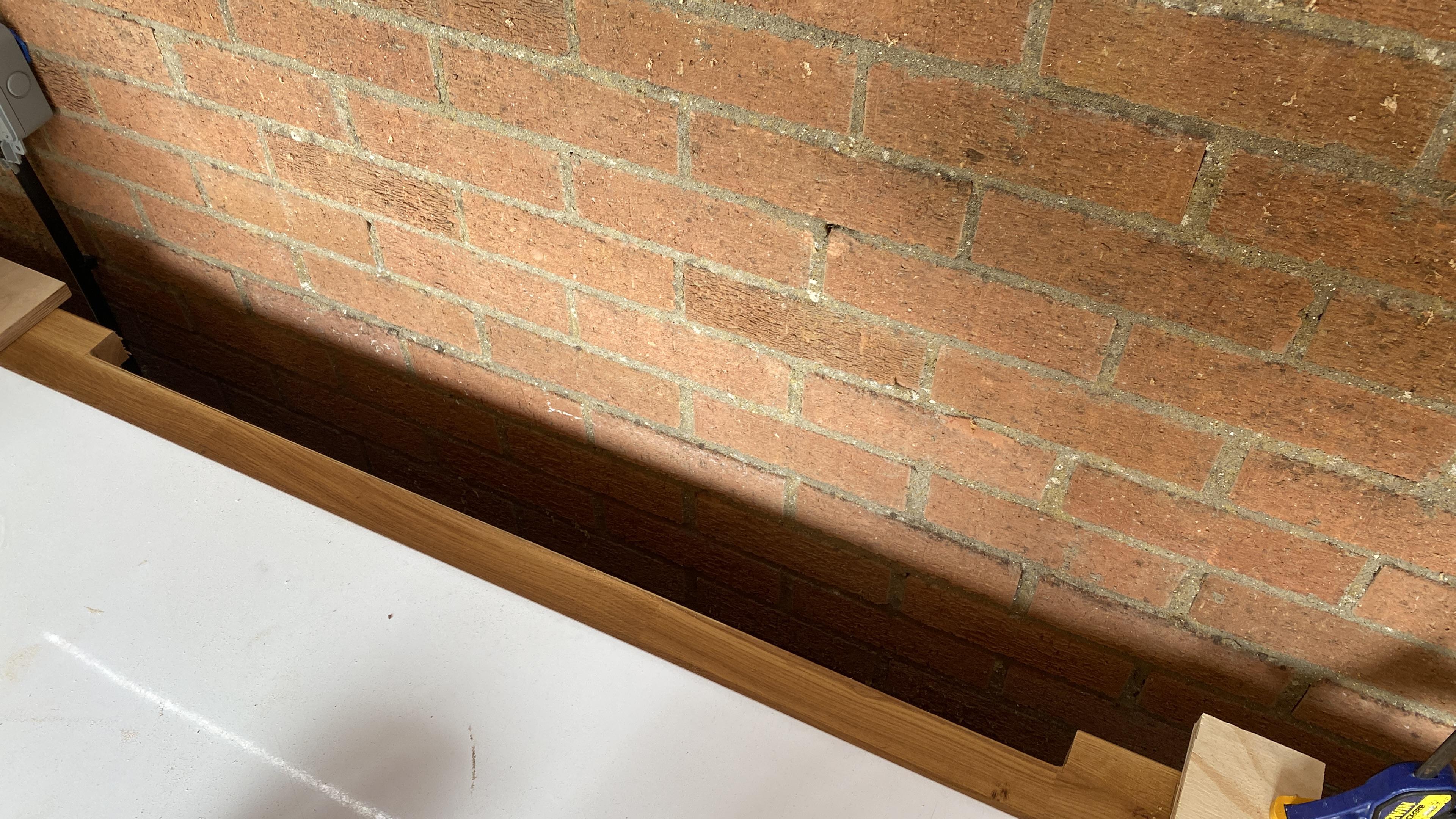
I cut out a notch in the back of the work surface to allow the cabinet to fit, aided by a 3D printed locating jig.
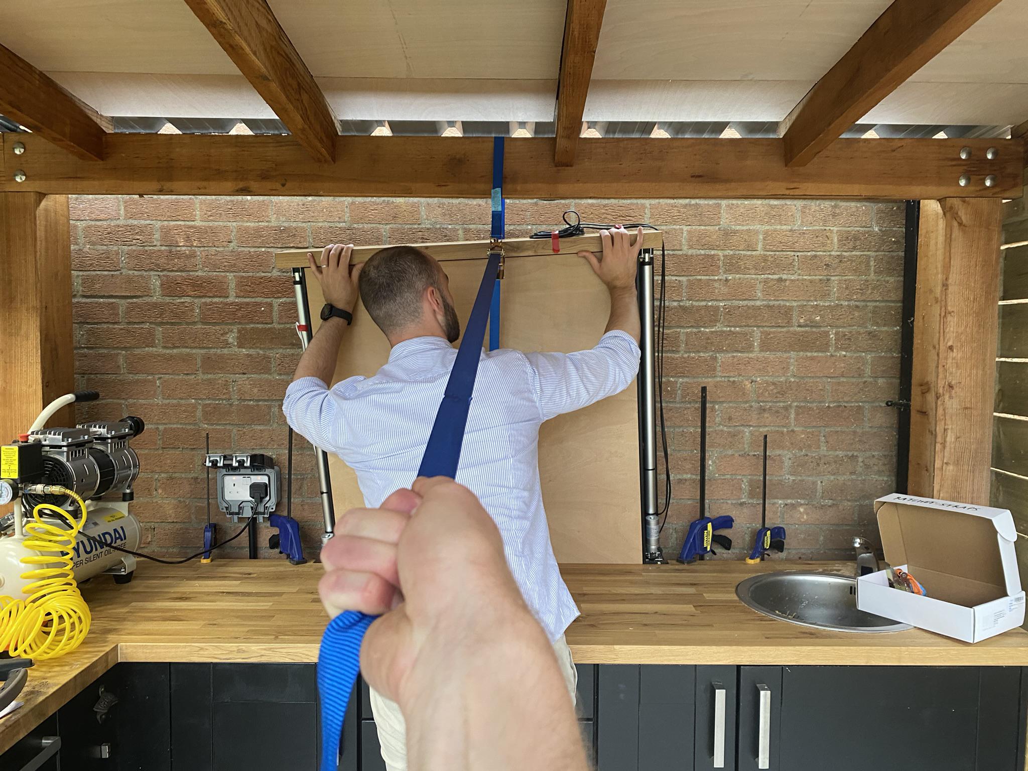
The cabinet was extremely heavy, and the gap was rather tight. This meant that I couldn’t just slide it into place without causing some damage. I used a ratchet strap around the roof support to gradually lower the cabinet into place with help from my brother.
There is a limited measure tool available but it’s too limited. ↩︎
Automatic hand washing tap
2025
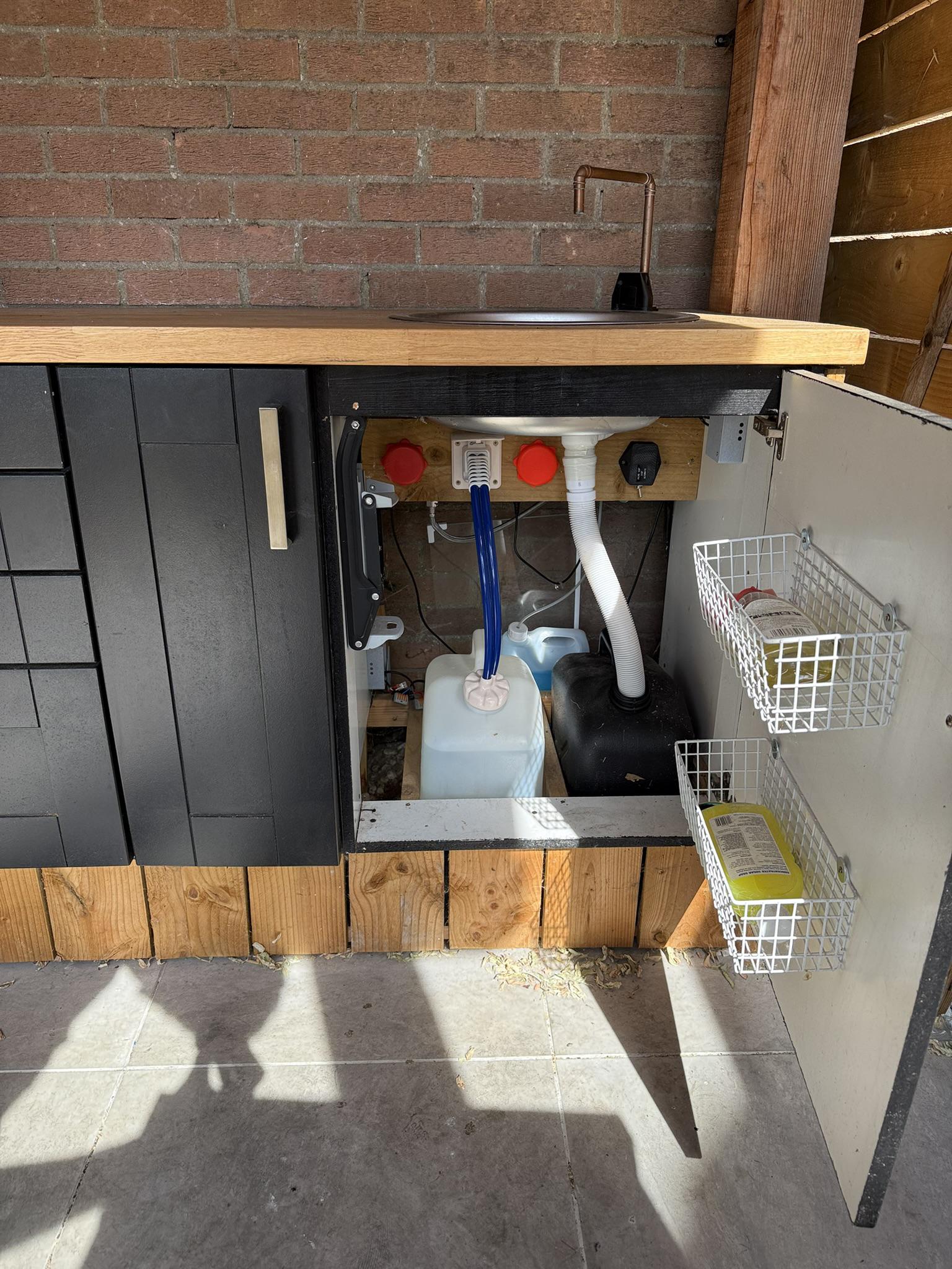
In 2023 I added a sink, complete with a caravan water pump and tanks to allow for hand washing + cleaning things when barbecuing.
I started with a (worryingly cheap) off-the-shelf automatic sensor tap combined with a pump socket that had a built-in pressure sensor. The tap was battery powered so I converted it to run on the same 12V drinks cabinet power supply with a 5v converter. This worked fine for a while, but had a downside – if the tank got empty the pressure sensor would activate and run the pump dry risking damage.
I ran this for a while, but a year later the pressure sensor stopped working – so I wired the sensor straight to the pump with a relay. It was necessary to use a timer module too, as the pump would otherwise run for a split second – that’s because the tap solenoid valve was bistable to save on battery power, given it was originally designed to run on batteries.
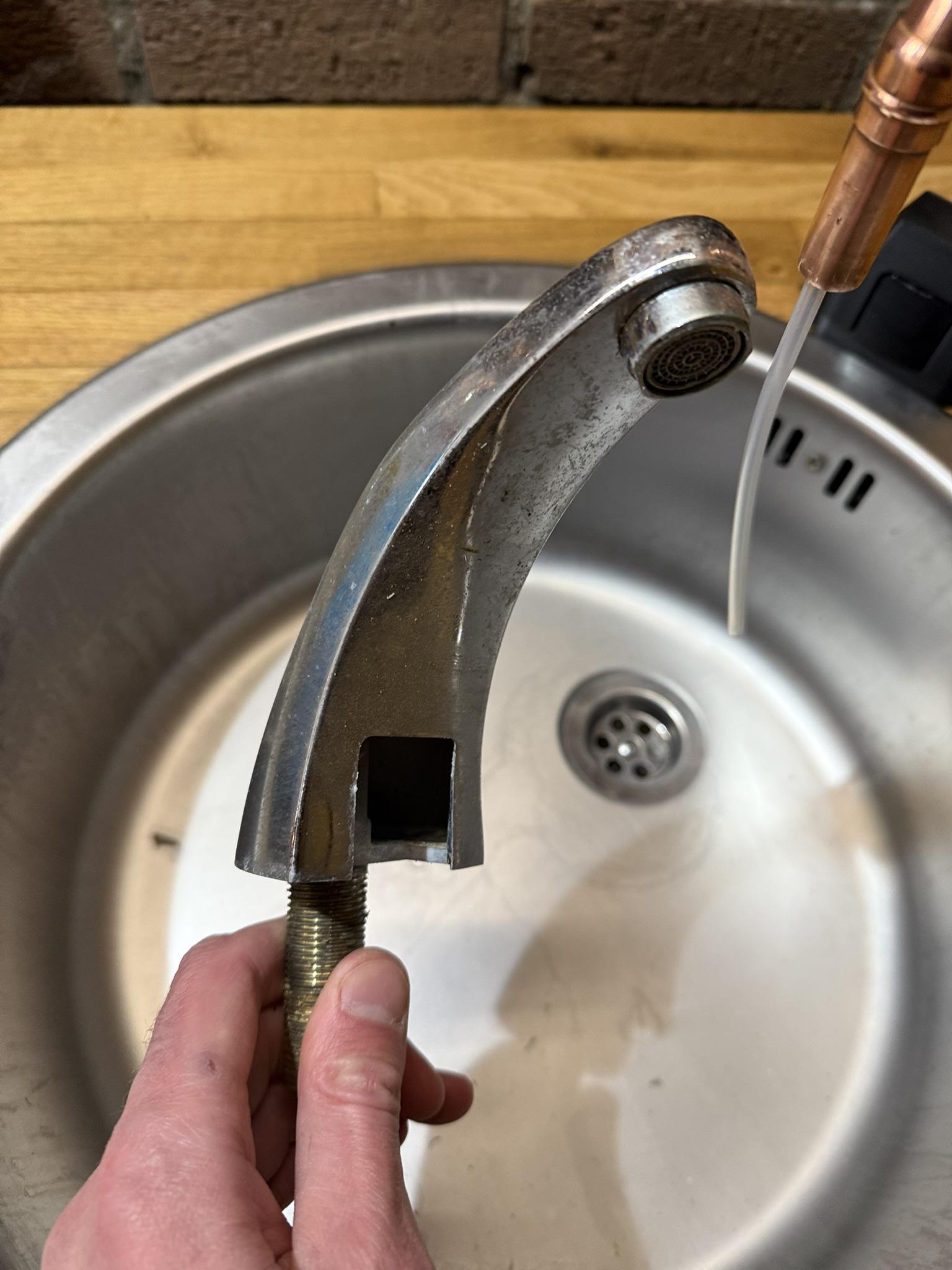
Annoyingly, I noticed pooling of water around the tap – the tap had cracked, likely in the winter due to frost. I had to re-work the whole thing, and figured I may as well add a soap dispenser in the process.
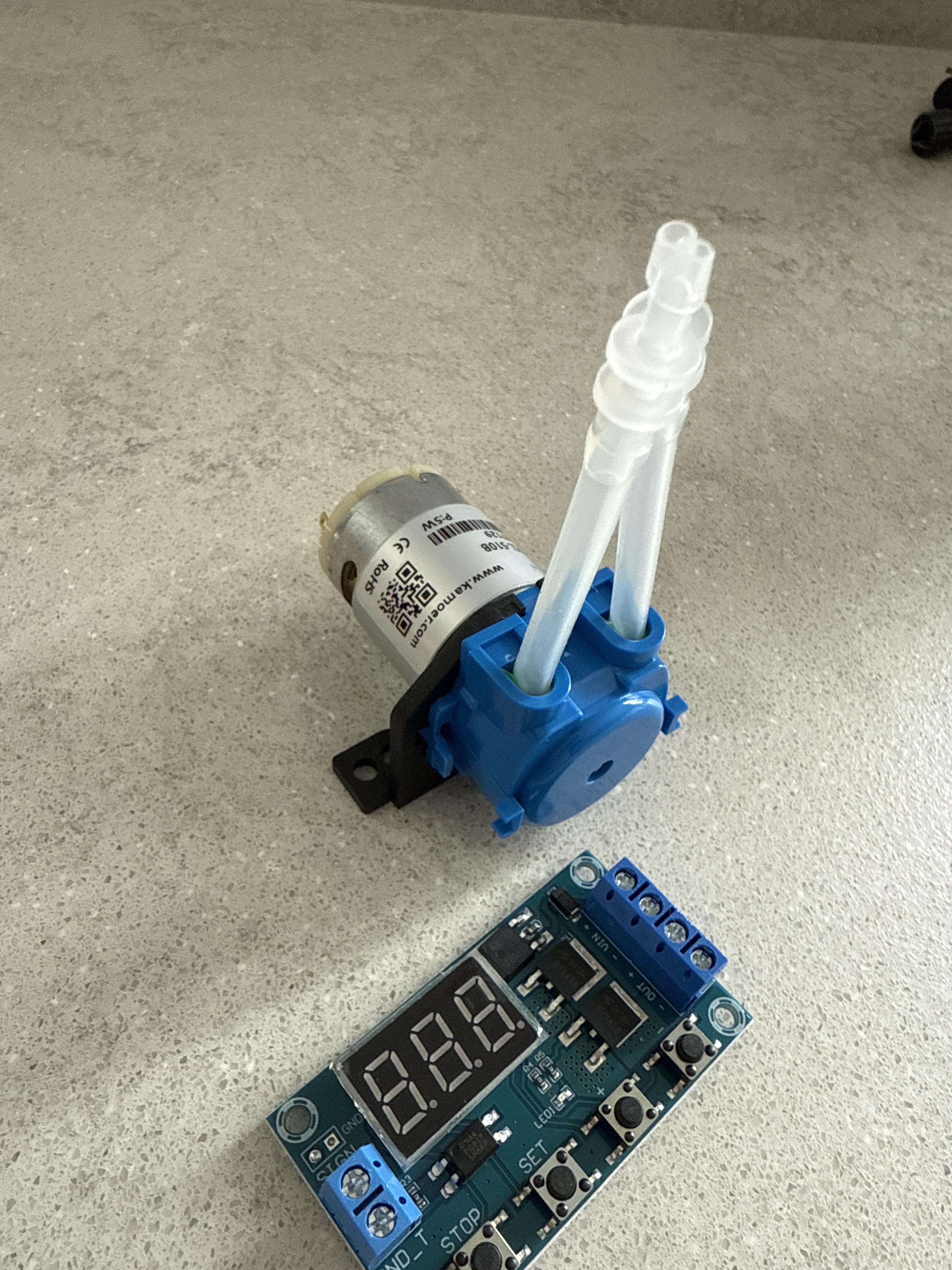
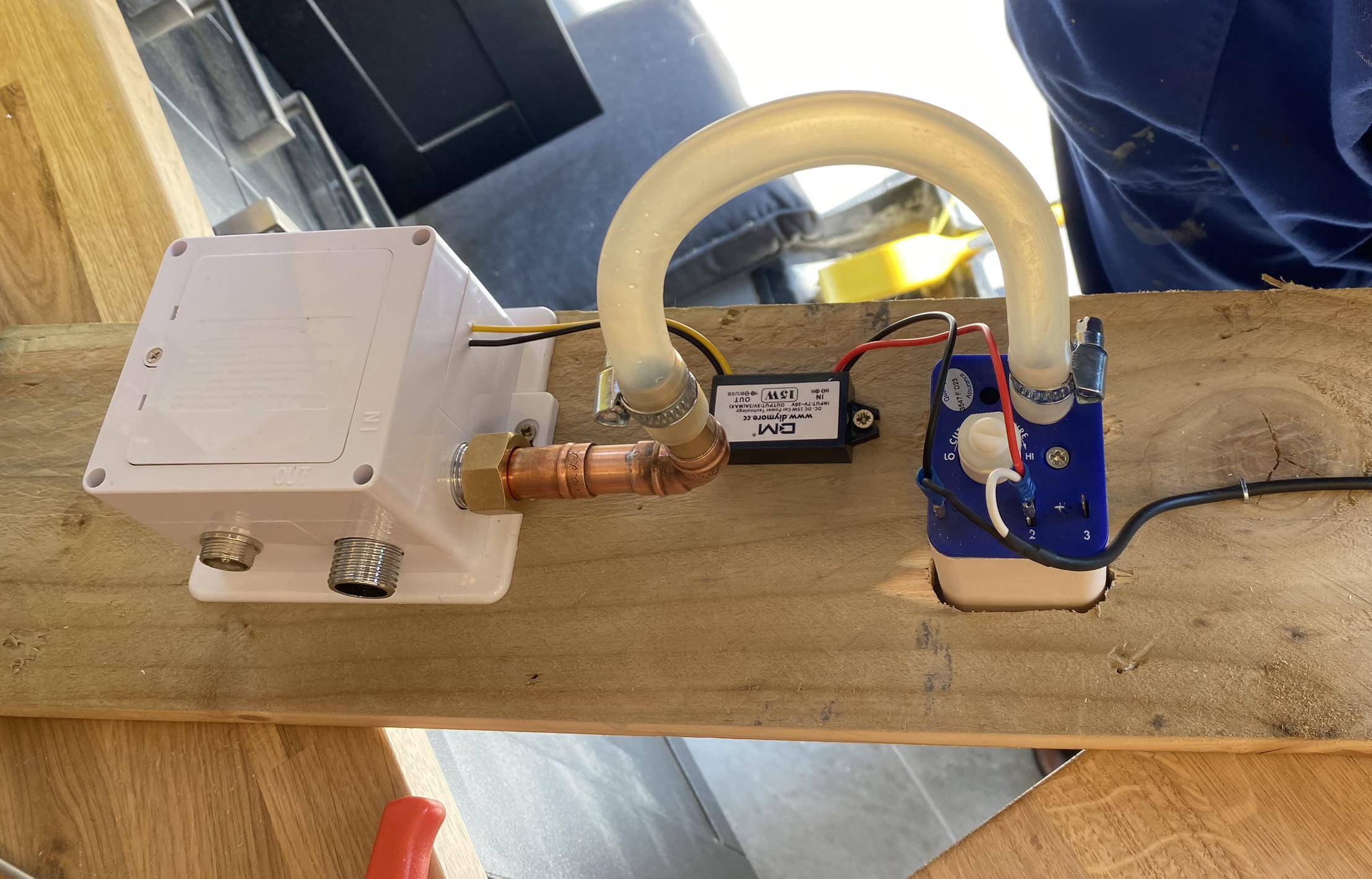
I’d heard of peristaltic pumps before – ideal for pumping soap as they are self-priming. They work by massaging the tube! I got a few cheap units and plumbed them in parallel.
If I could figure out a way of putting a silicone soap pipe inside a larger water pipe, I could make a tap that can dispense both. If I grabbed the sensor from the old tap, with some timers and relays, I could make a fully automatic soap/water tap.
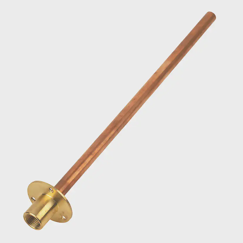
I settled on a union back plate (intended for a garden hose spigot) and soldered some 15mm copper piper for the main tap body. This was surprisingly solid, and I didn’t have to buy any copper pipe as it had 600mm attached already!

As for the silicone tubing, I got a bulkhead adapter to allow sealing against the copper pipe, and a tee connector to make it easy to connect water and soap at the same time.
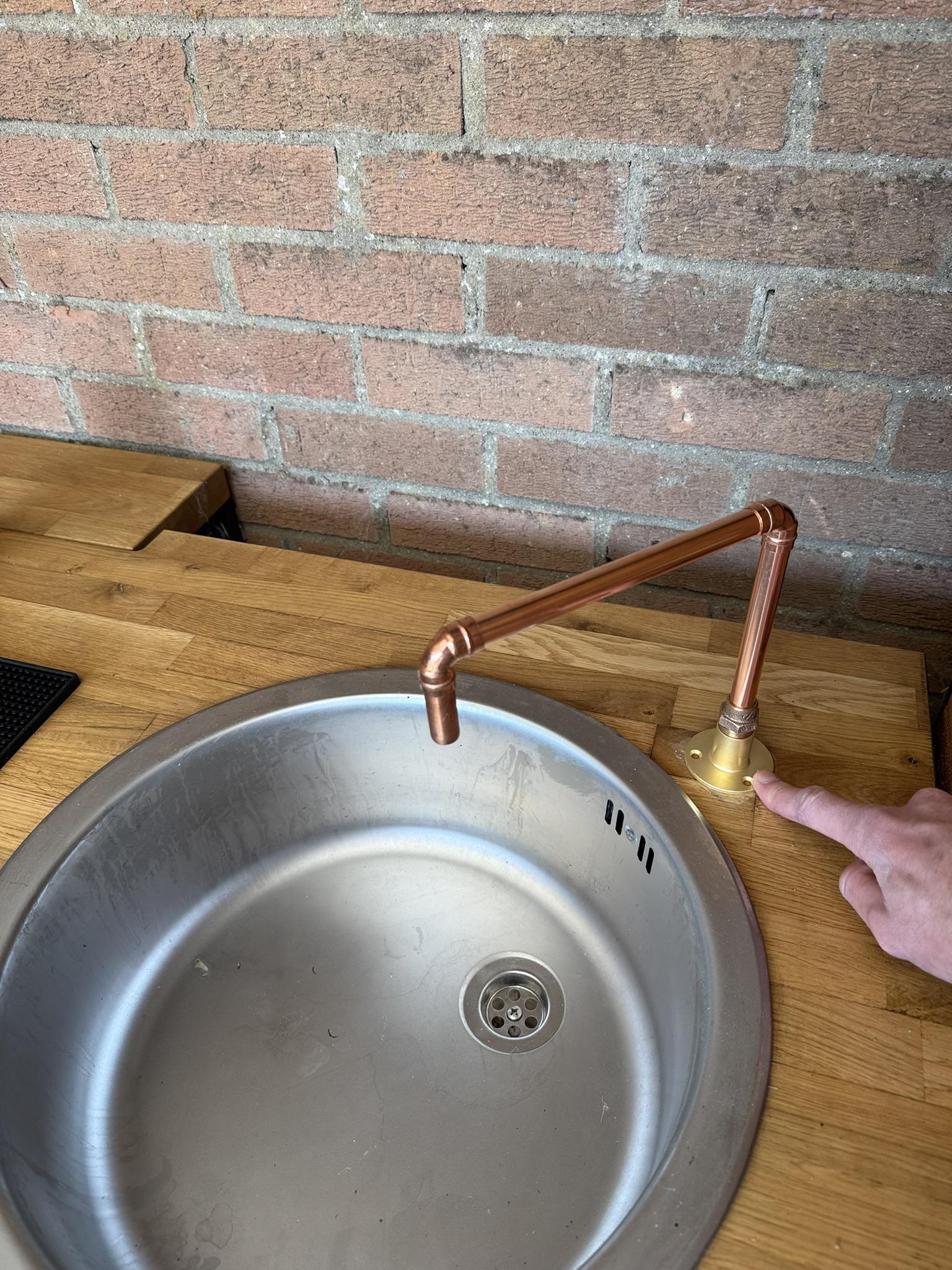
I used a vacuum cleaner to get the tubing through the pipe, by sucking through a piece of string first and using that to pull the tubing through. I 3D printed a concentric insert to hold the tube in the middle of the outlet.
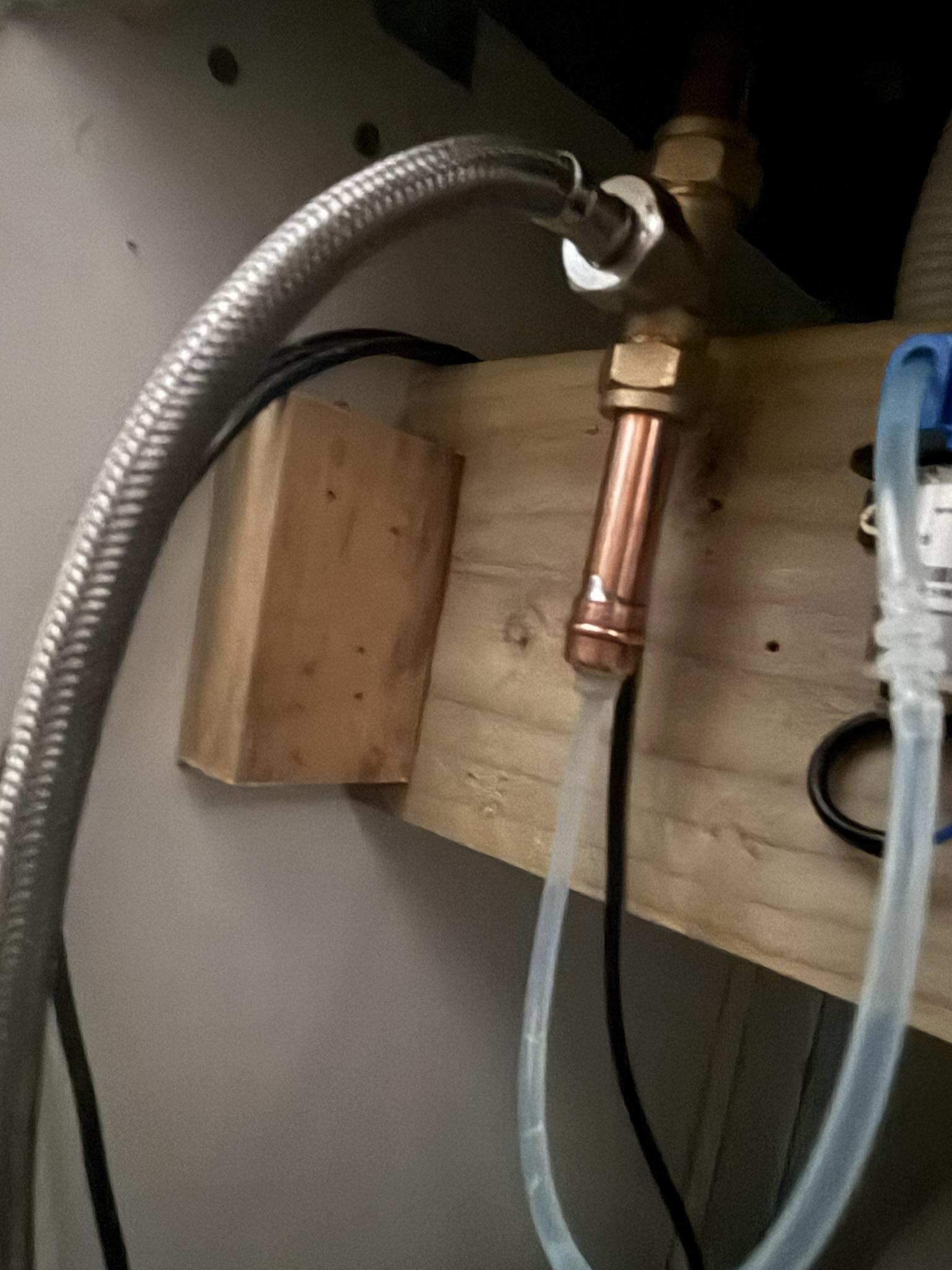
As for the sensor block, I designed a quick enclosure to hold it in roughly the same place, together with an interposer to allow it to fit in between the sink lip and the union plate.
I had only a weekend, so I didn’t want this to end up being a huge project. I could have made a custom controller board, but there was not point as I had several timers, relays and regulator modules in stock. The basic diagram is above – the first timer activates the soap pump and is on for the whole duration; the second timer switches from the soap pump to water pump after 3 seconds. This way, re-triggering does not re-trigger the soap which would be annoying.
The above video shows the system in action. Luckily the messy wiring is hidden…3 This is before I added a manual override switch to prime the soap pump; it got even messier after that!
I added a buck converter module to reduce the voltage to the water pump in the end, as it was a bit much – it’s a high flow rate model designed for caravan showers.
I could have used off-the-shelf home automation relays too; though I deliberately didn’t – there’s something to be said for standalone automation. This simple automation won’t fail if the internet or server goes down!
Except of course, now everyone can see… ↩︎
BBQ cart
2025
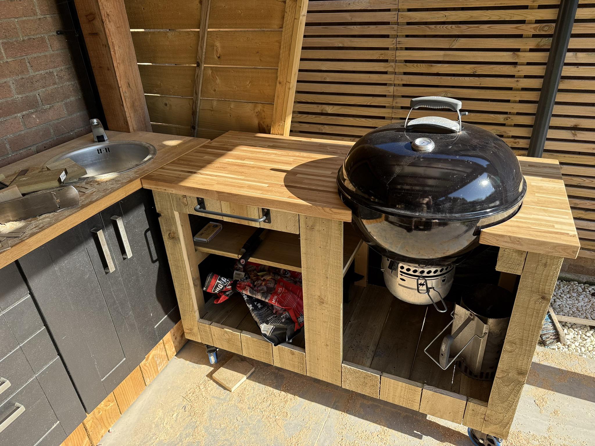
We’ve had a Weber kettle BBQ charcoal4 for around 10 years. It was still going strong but was always annoyingly low down for me (I’m 6'5") and didn’t have a work-surface next to it. It was also a pain to store the charcoal and tools.
For this part of the bar I didn’t take many pictures unfortunately. However, it’s a simple construction – CLS timber with woodscrews and casters. Like the rest of the bar, it is clad in 22x150mm sawn timber nailed into place with my 16ga nail gun.
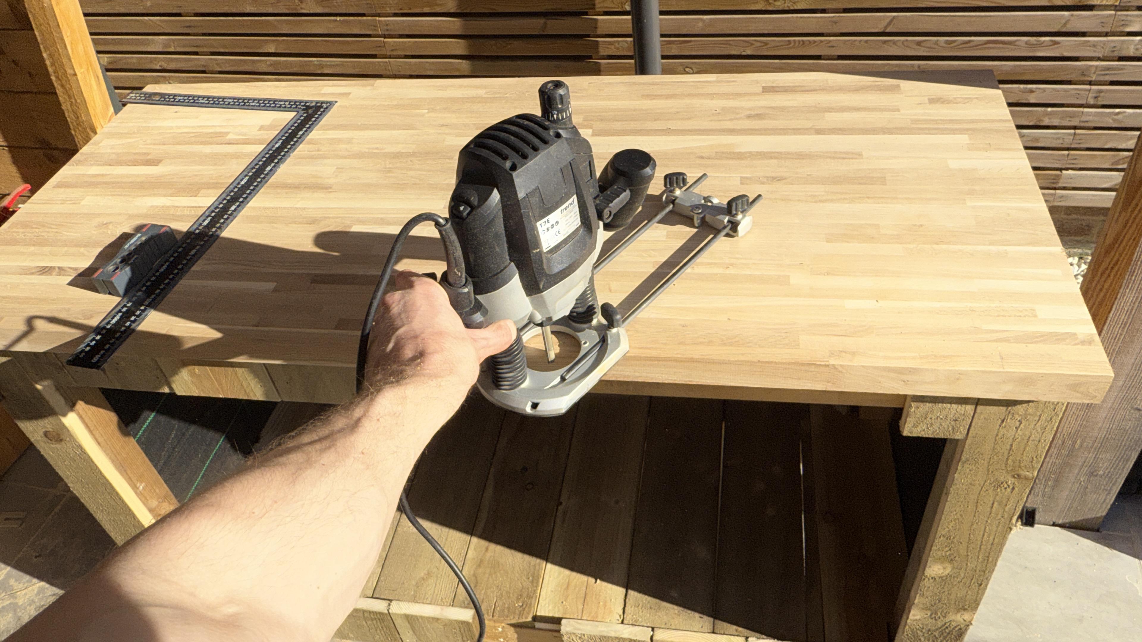
I got some butcher block worktop and cut it to size for a 20mm overhang. To ensure I didn’t end up with thin sections, I offset the BBQ to the front when cutting the circle with a 1/2 in router + compass.
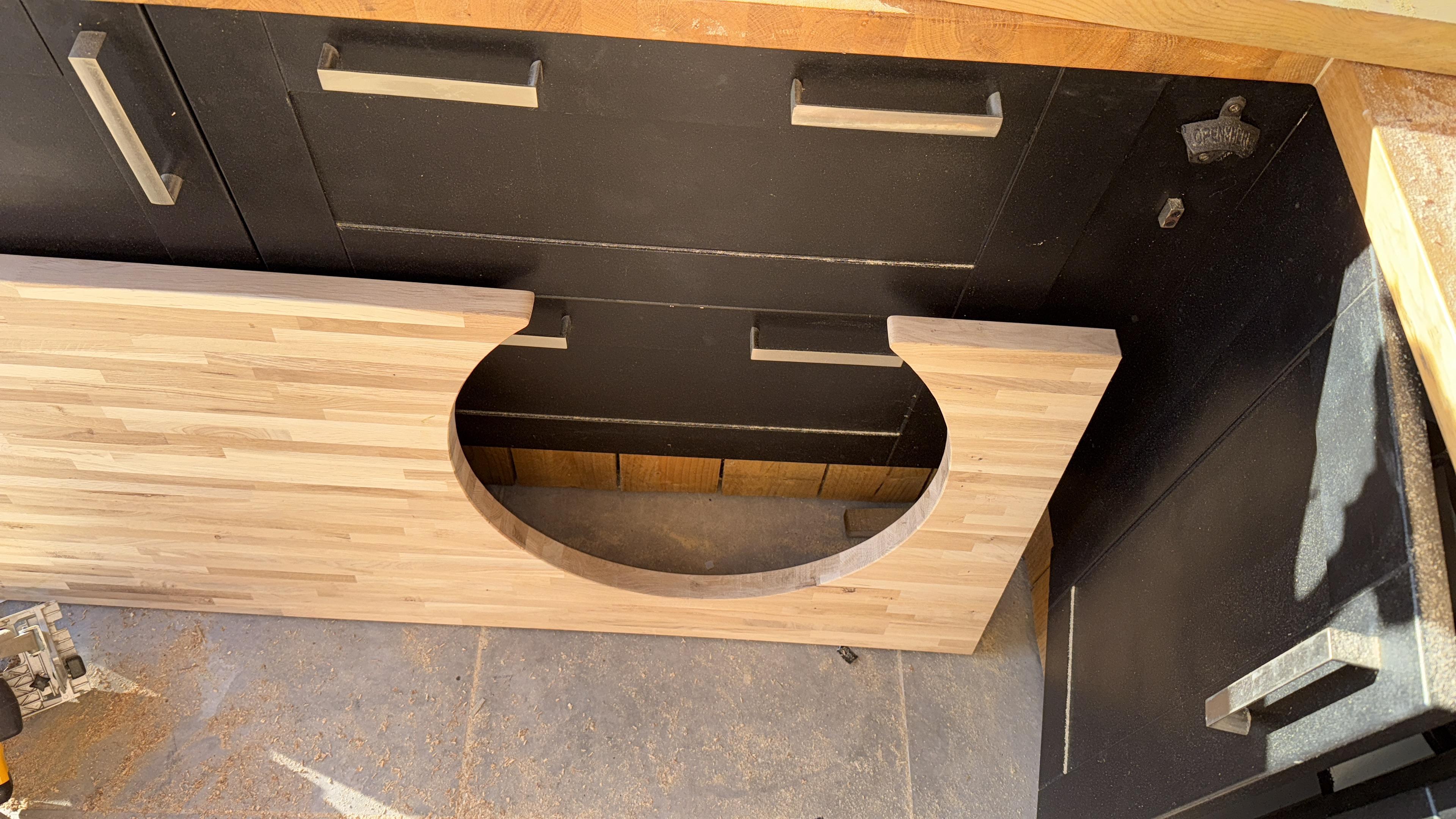
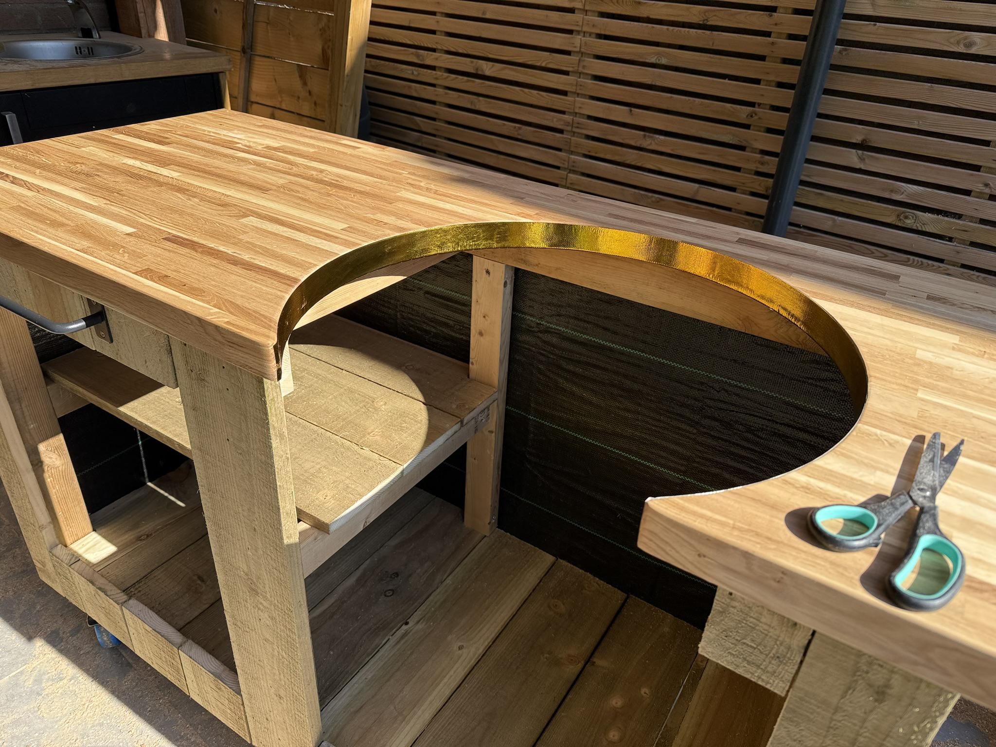
I used some stainless brackets, installed with some cobalt drill bits to hold the BBQ in place with a 15mm or so gap around the edge. I added some gold heat reflecting tape to the edges of the worktop to further protect it – 6 BBQs later it hasn’t cracked warped or scorched!
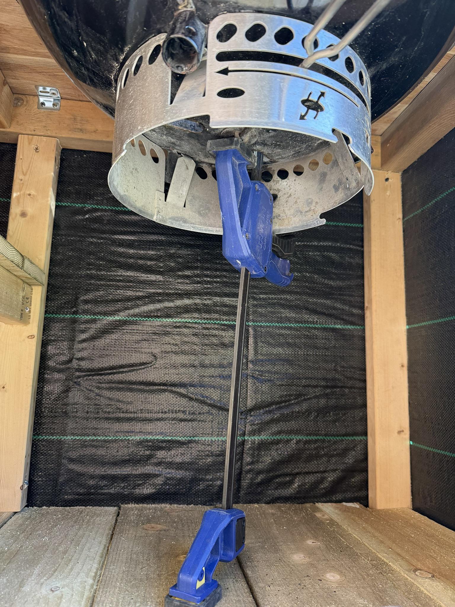
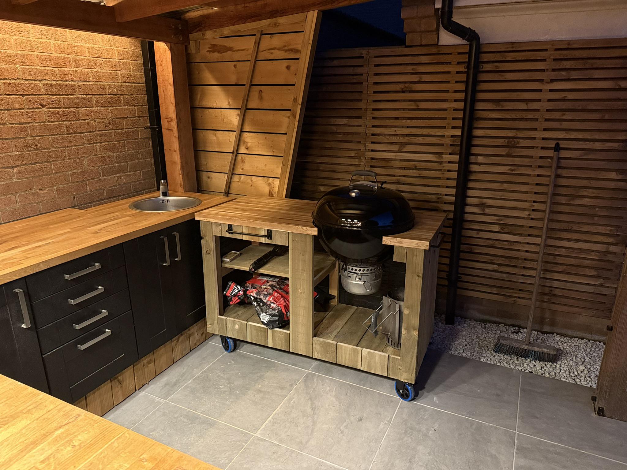
I levelled the cart – and lined it up with the counter-top – using some parametric 3D printed interposers.
The only way to BBQ. If you want a gas BBQ, you may as well drink instant coffee too. ↩︎
Plant wall frame
2025
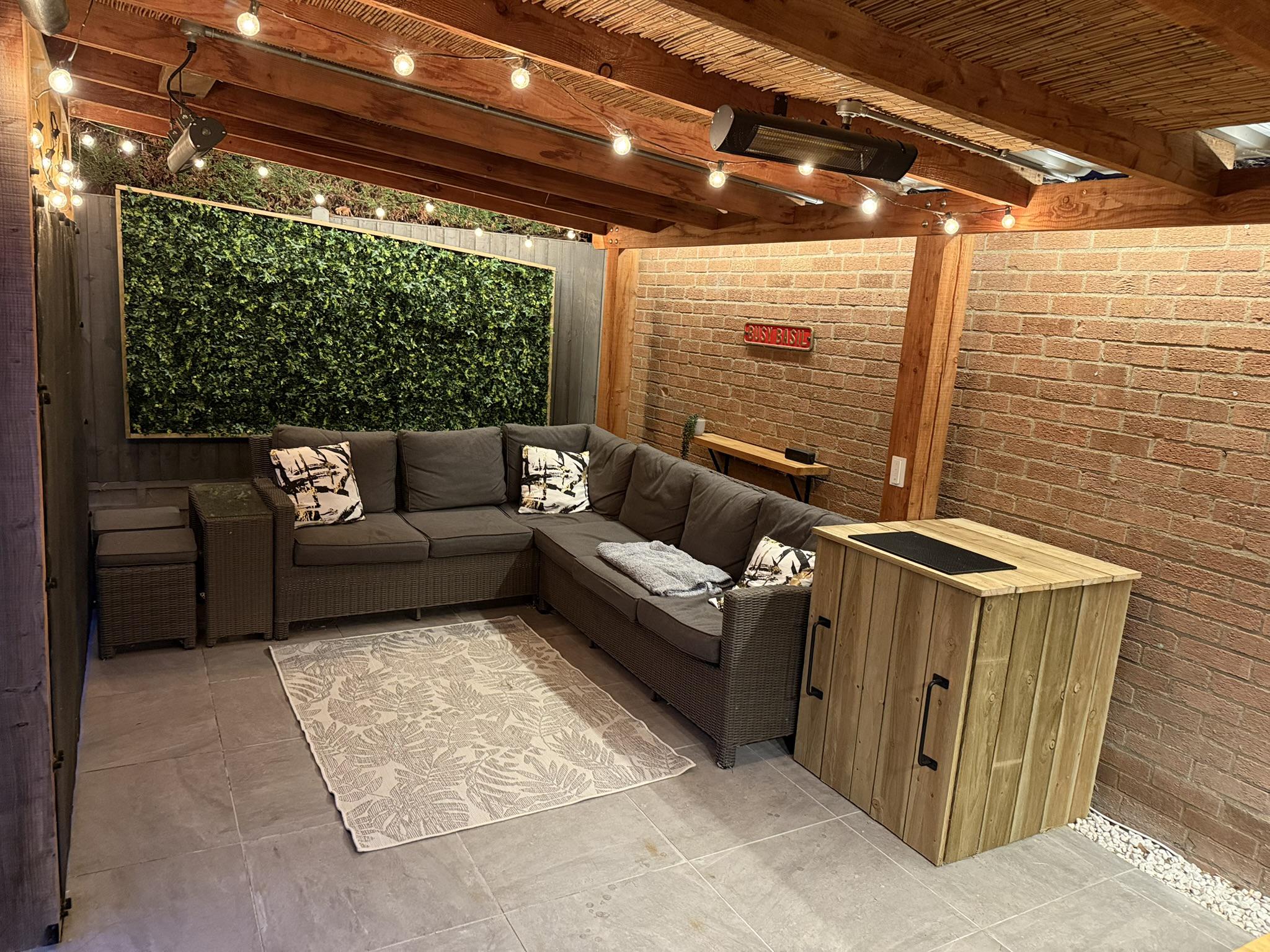
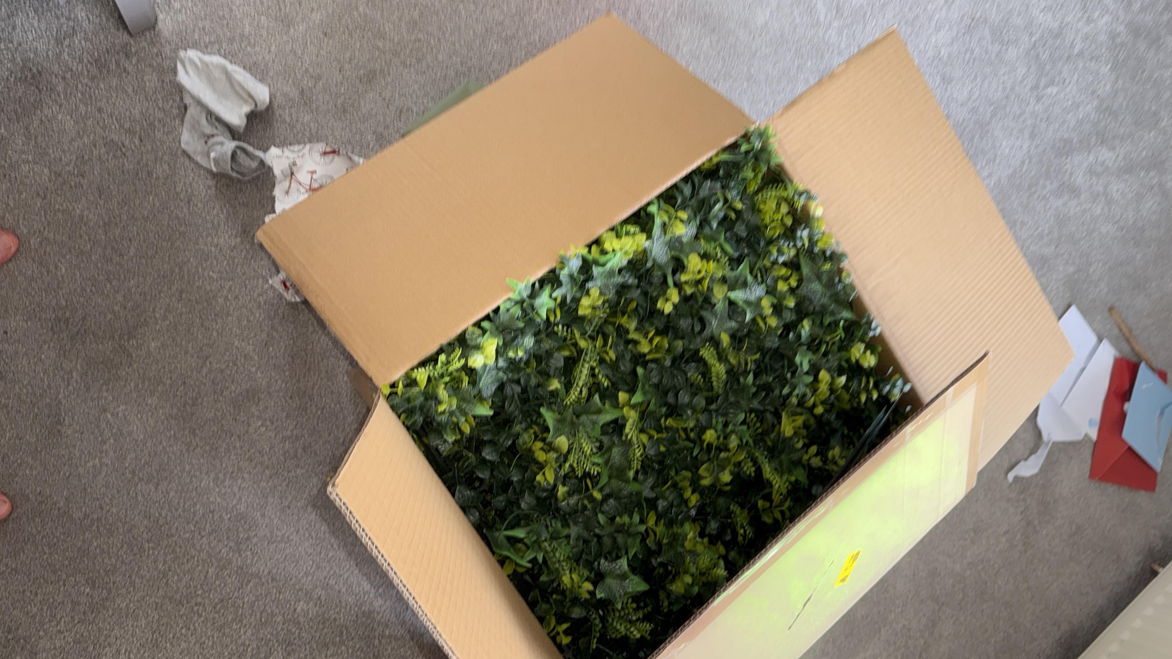
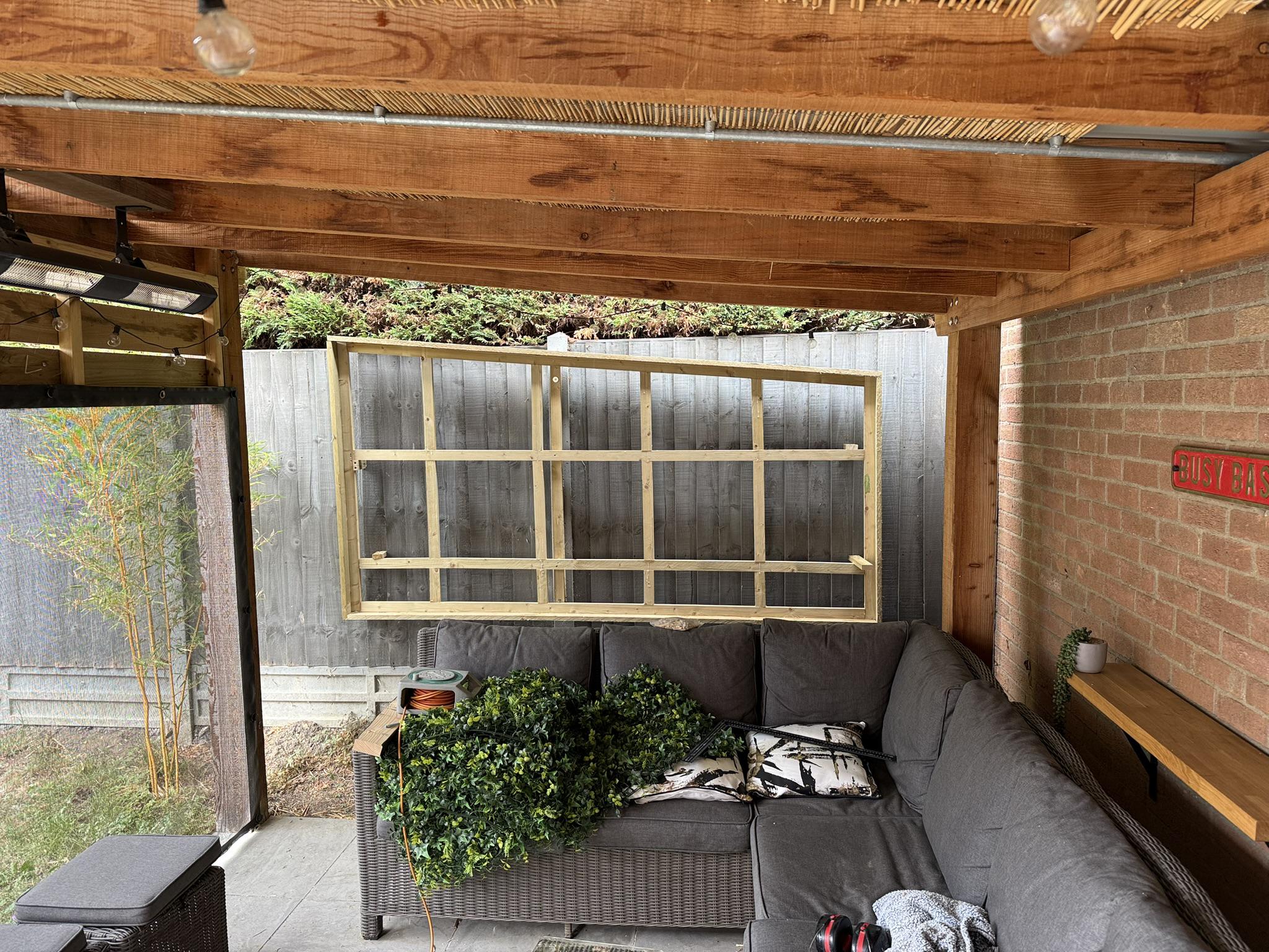
From family I got a box of fake plants for my birthday. My wife was happy as she had wanted me to build a plant wall behind the sofa for a while. I was worried that it might look tacky so I figured I needed to make an effort…
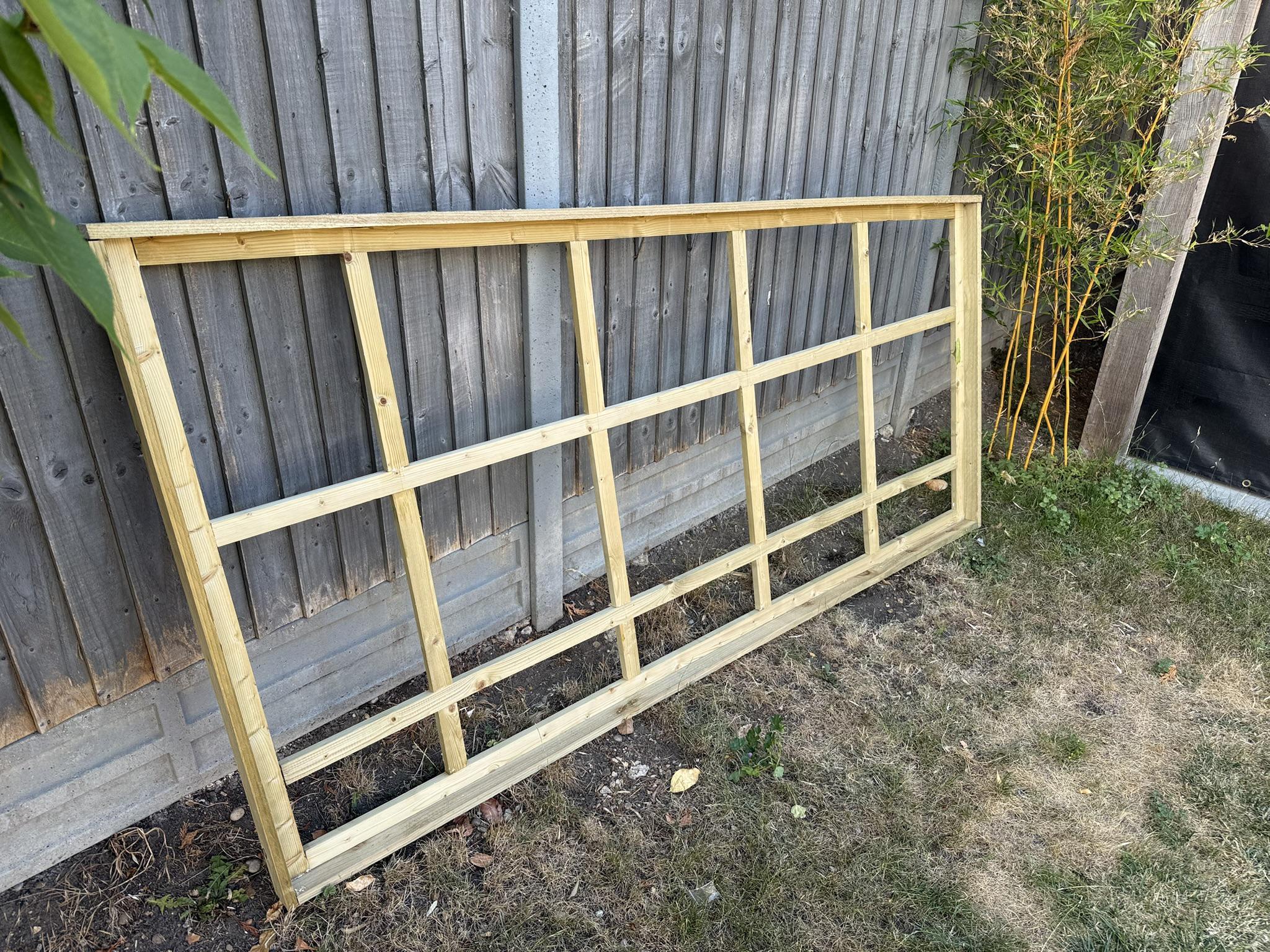
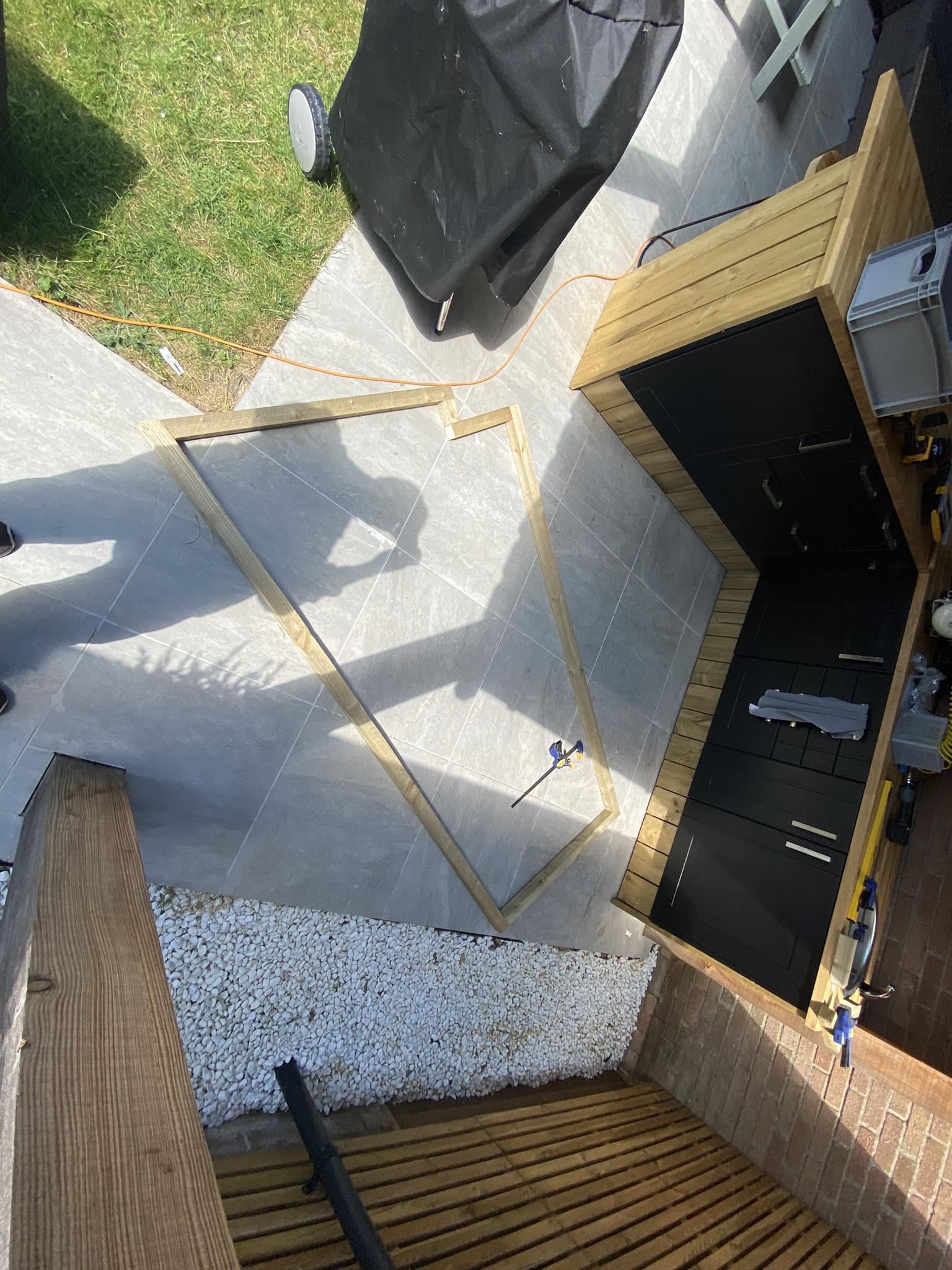
I settled on a building a frame from 20.5x44mm treated timber, laid out in a 500mm grid down flat to allow the 500mm panels to be stapled in place. I angled the top 5 degrees to follow the profile of the roof so it looks like it’s an intentional part of the main structure rather than a separate add-on.
I changed the dimensions of the frame to better fit the area, ensuring the total area was less than the 3m2 worth of plant panels I had.

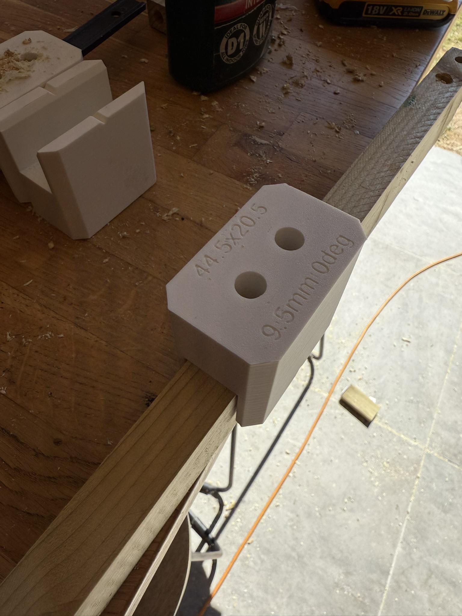
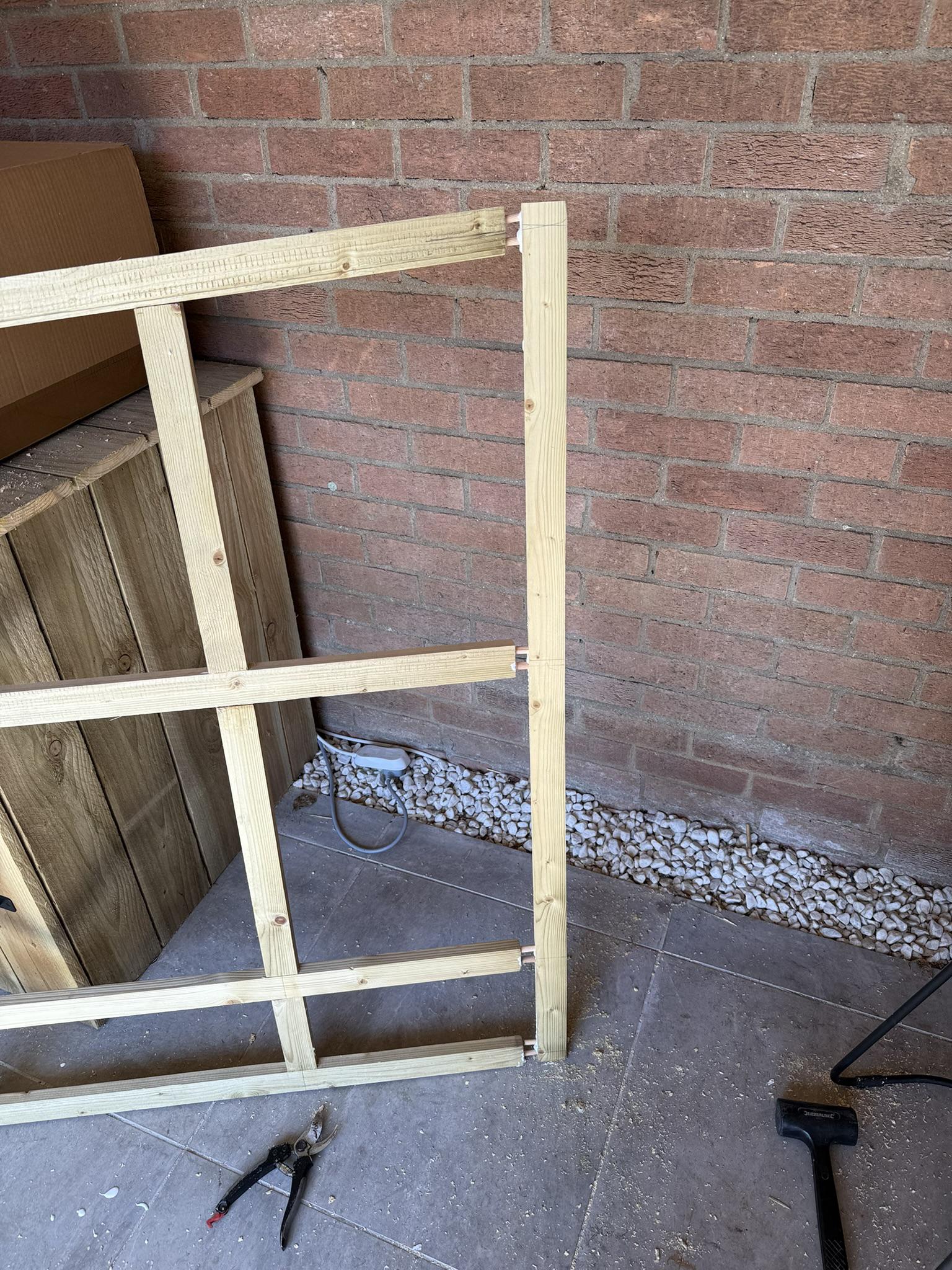
To join without lots of brackets I figured I’d try dowel joins. I could have got a dowel jig, but this sort of think is exactly why I have a 3D printer. I made some parametric dowel jigs in OpenSCAD sized for the wood with 6mm and 8mm dowels.
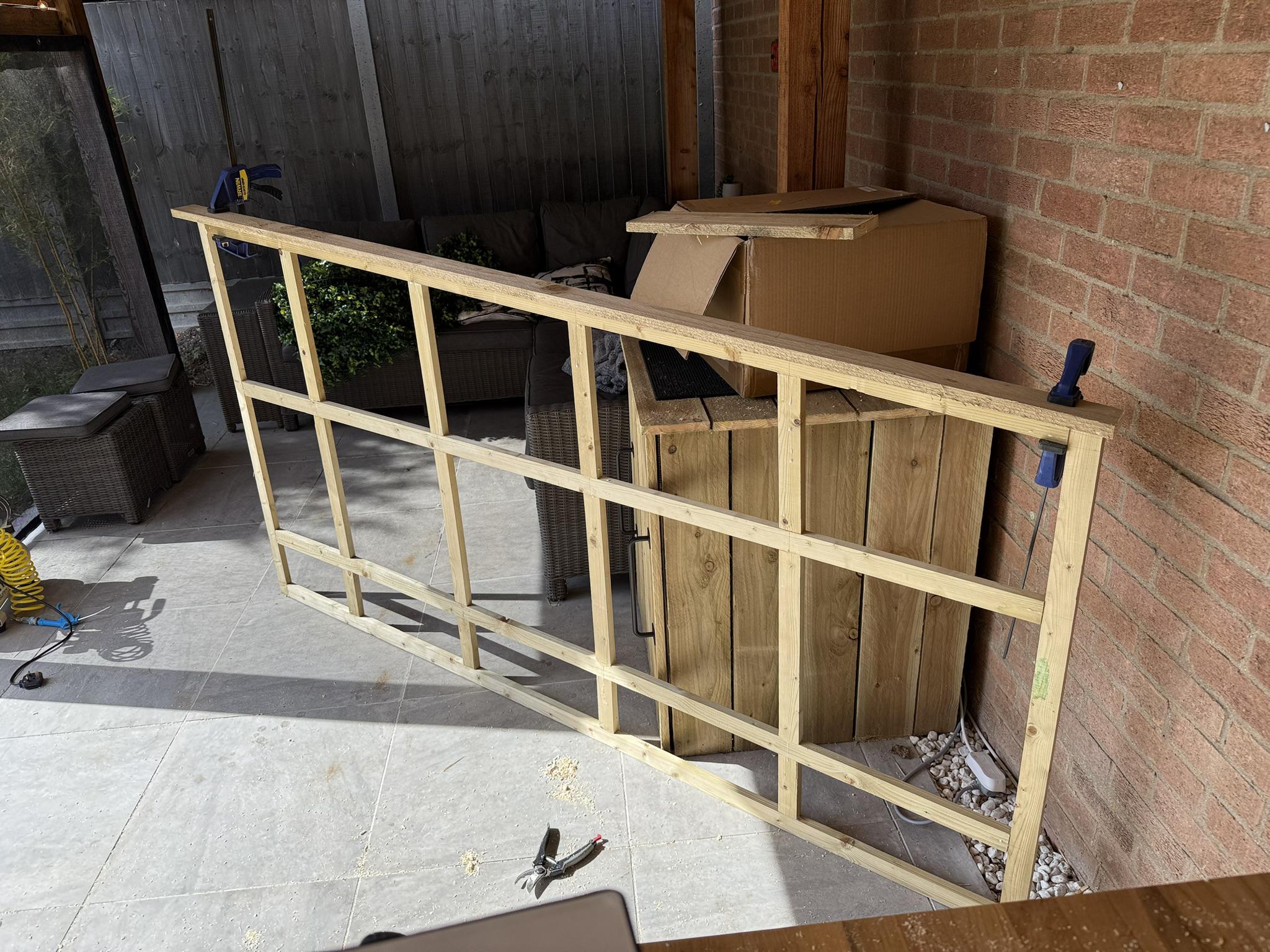
Framed the grid with the same 22x150mm sawn timber as the rest of the bar, but ripped in 2 with a circular saw.5 I used my 16ga nail gun to fix the frame in place.
It’s surprising how accurate you can be freehand with a sharp circular saw blade – the blade itself acts as a guide. I reckon I can get within 2mm or so repeatedly. ↩︎
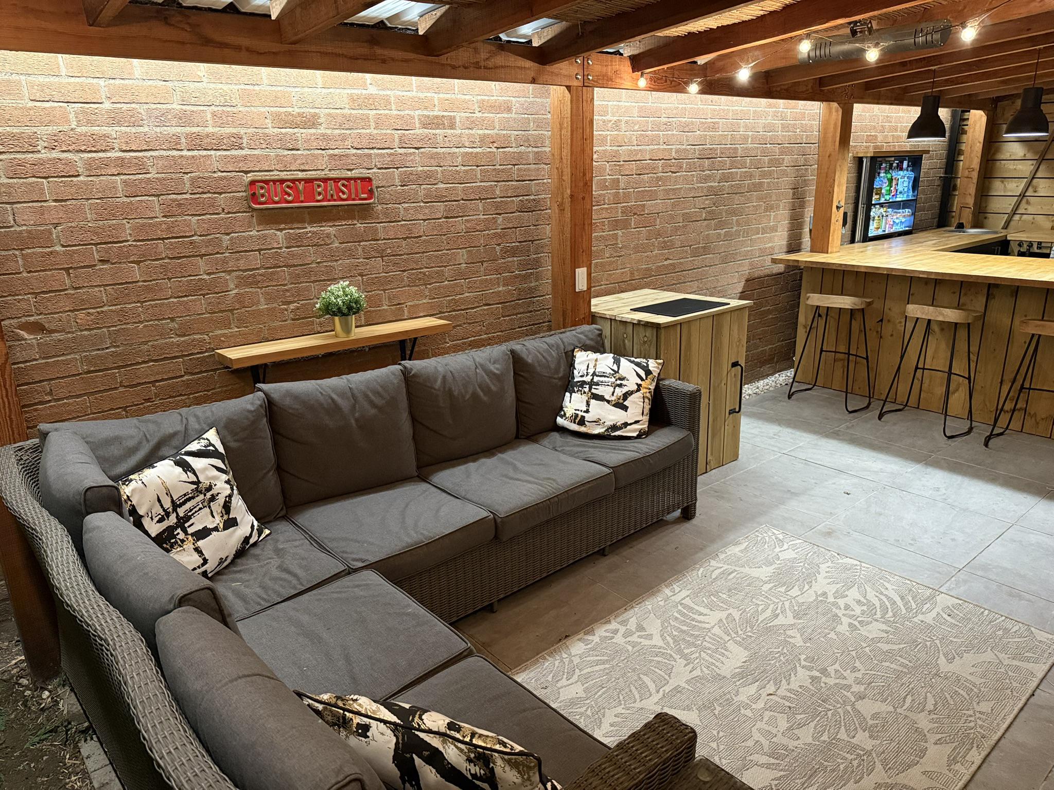
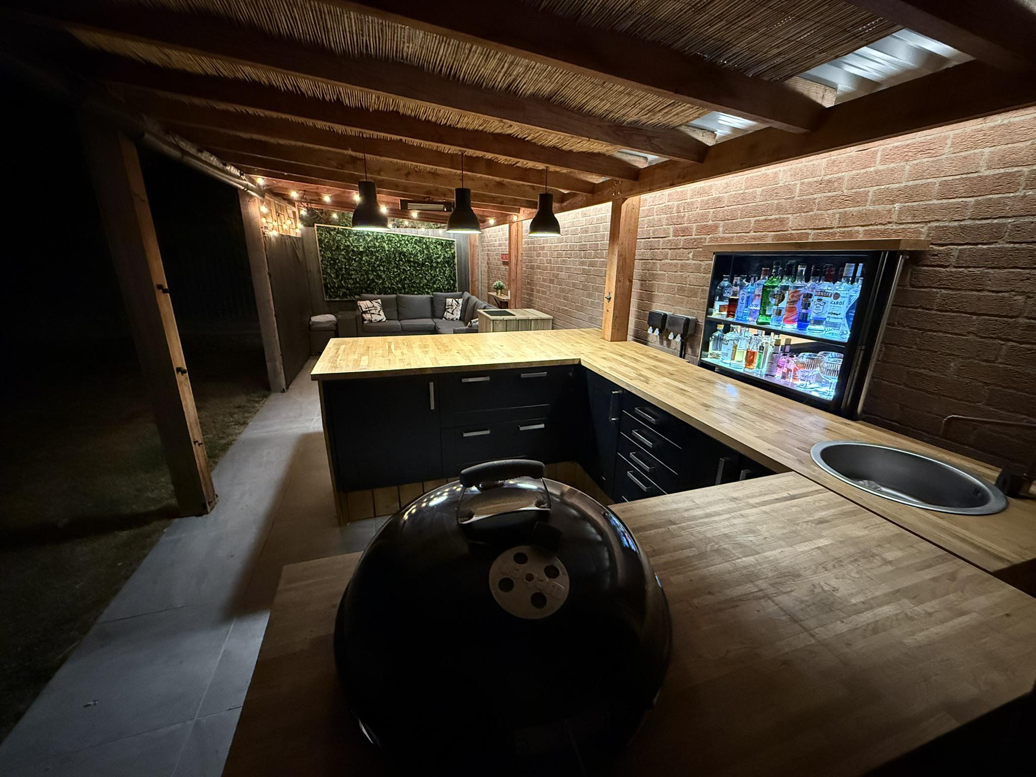
Bar kitchen cabinets
2023
Lessons learnt
- Wickes wood is always wet and always shrinks… Dry it first or use something else.
- Make sure the wood curves inwards not outwards
- 16ga nails are needed for the wood trim
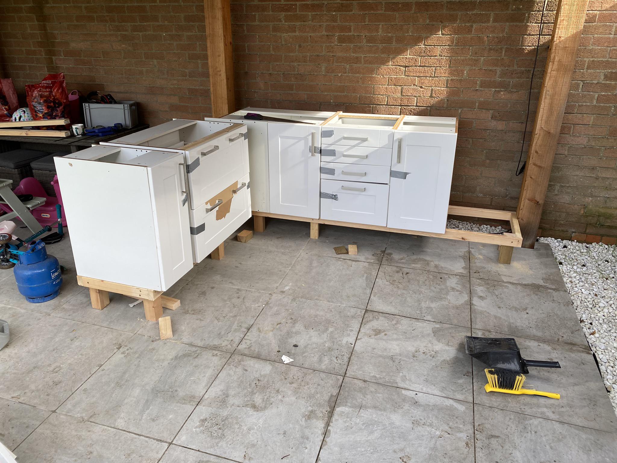
Having renovated our kitchen, we had a lot of spare cabinets. Moving them outside motivated me to build the bar kitchen.
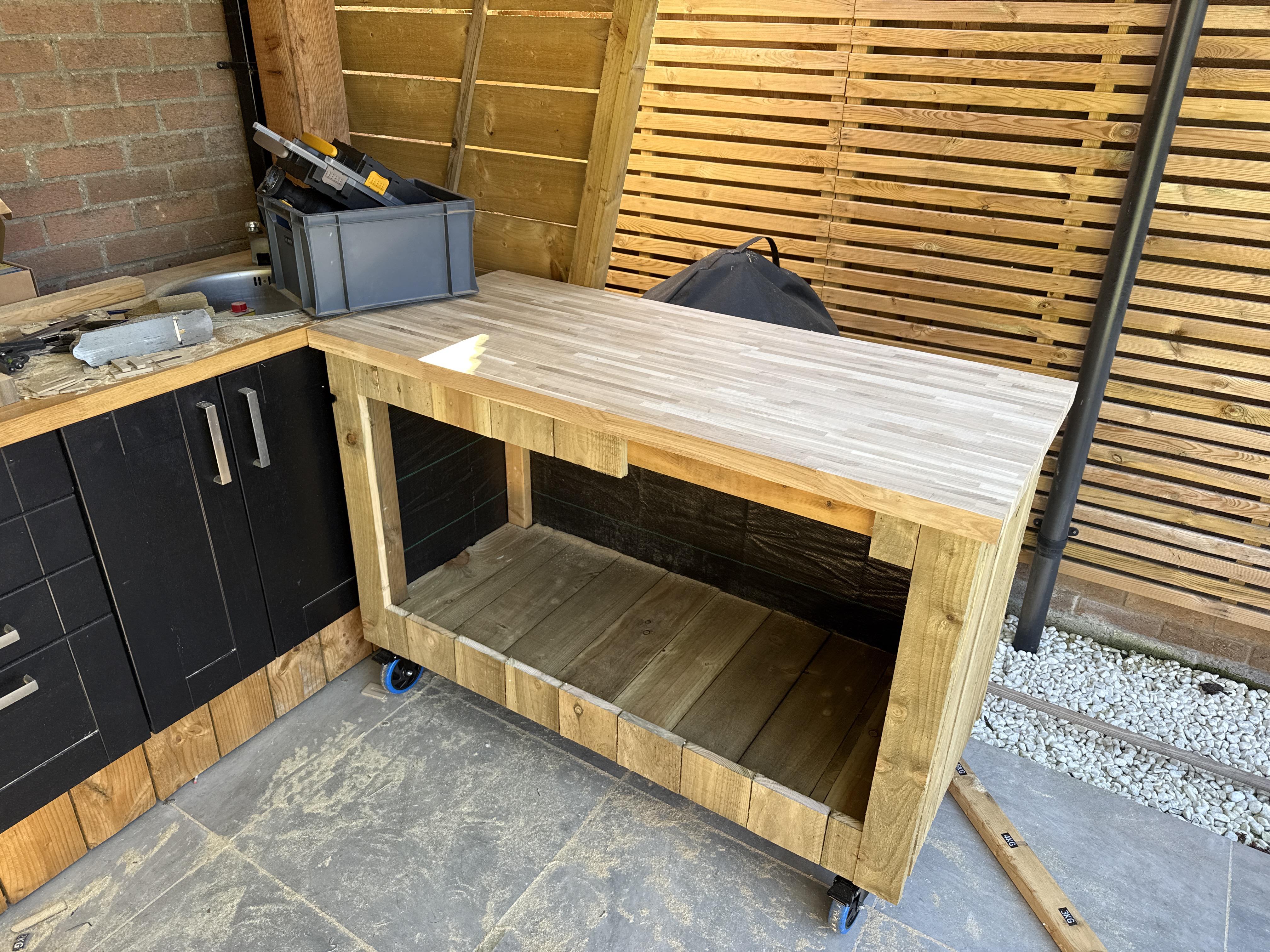
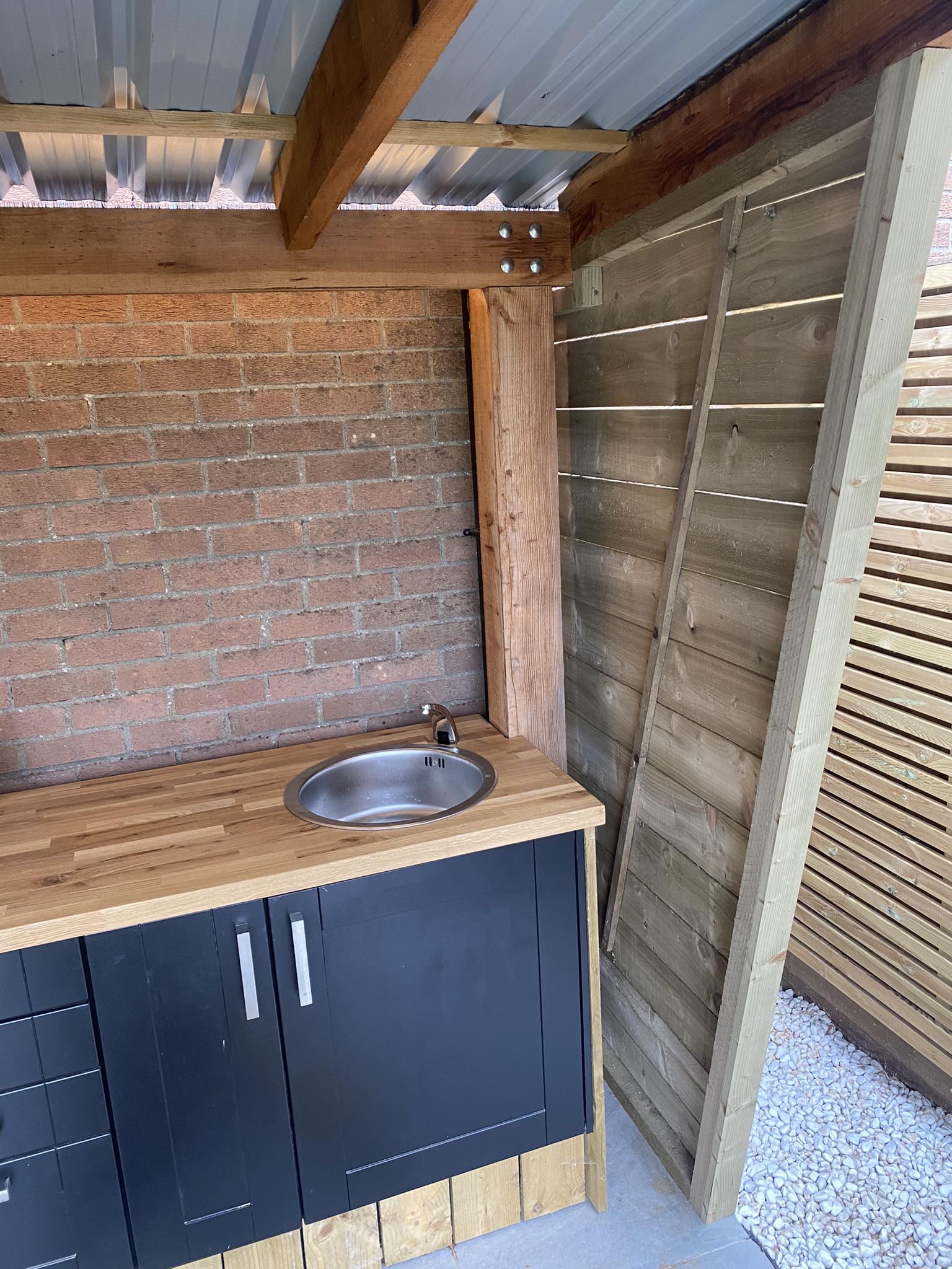
I built a sub-frame out of 47x97mm CLS timber, screwed together and set for a cabinet height of about 900mm – a bit taller than a standard kitchen worktop to suit my height.
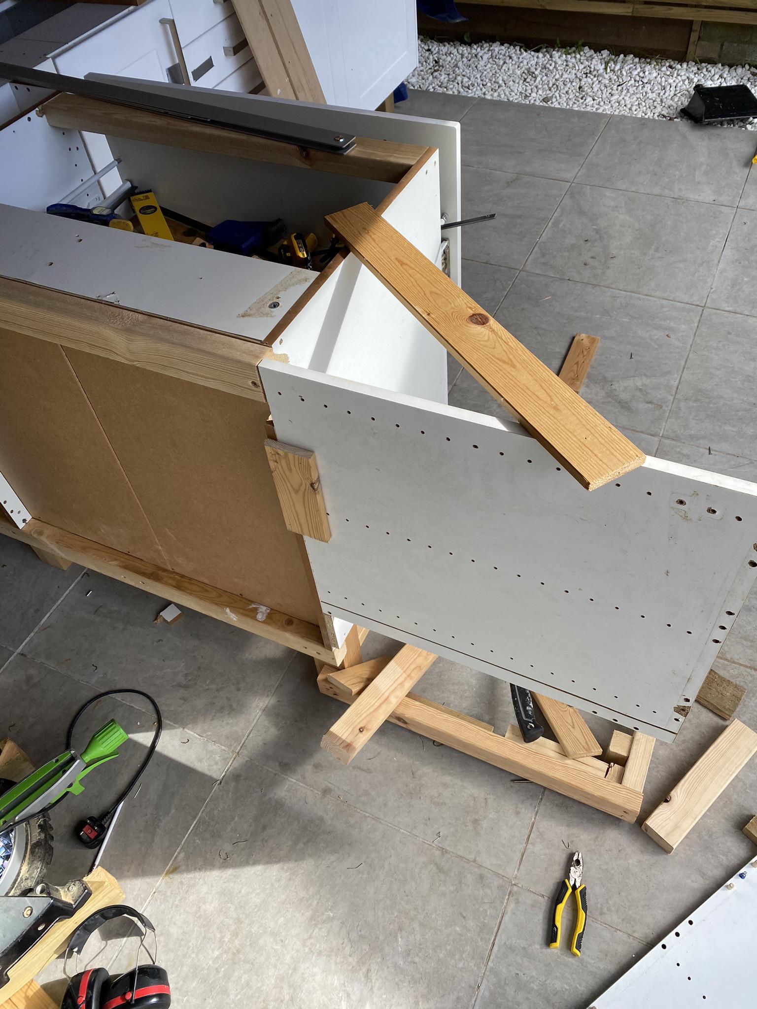
The 18ga nail gun came in handy to build the (single panel) fridge enclosure, holding the panels in place before securing with screws.
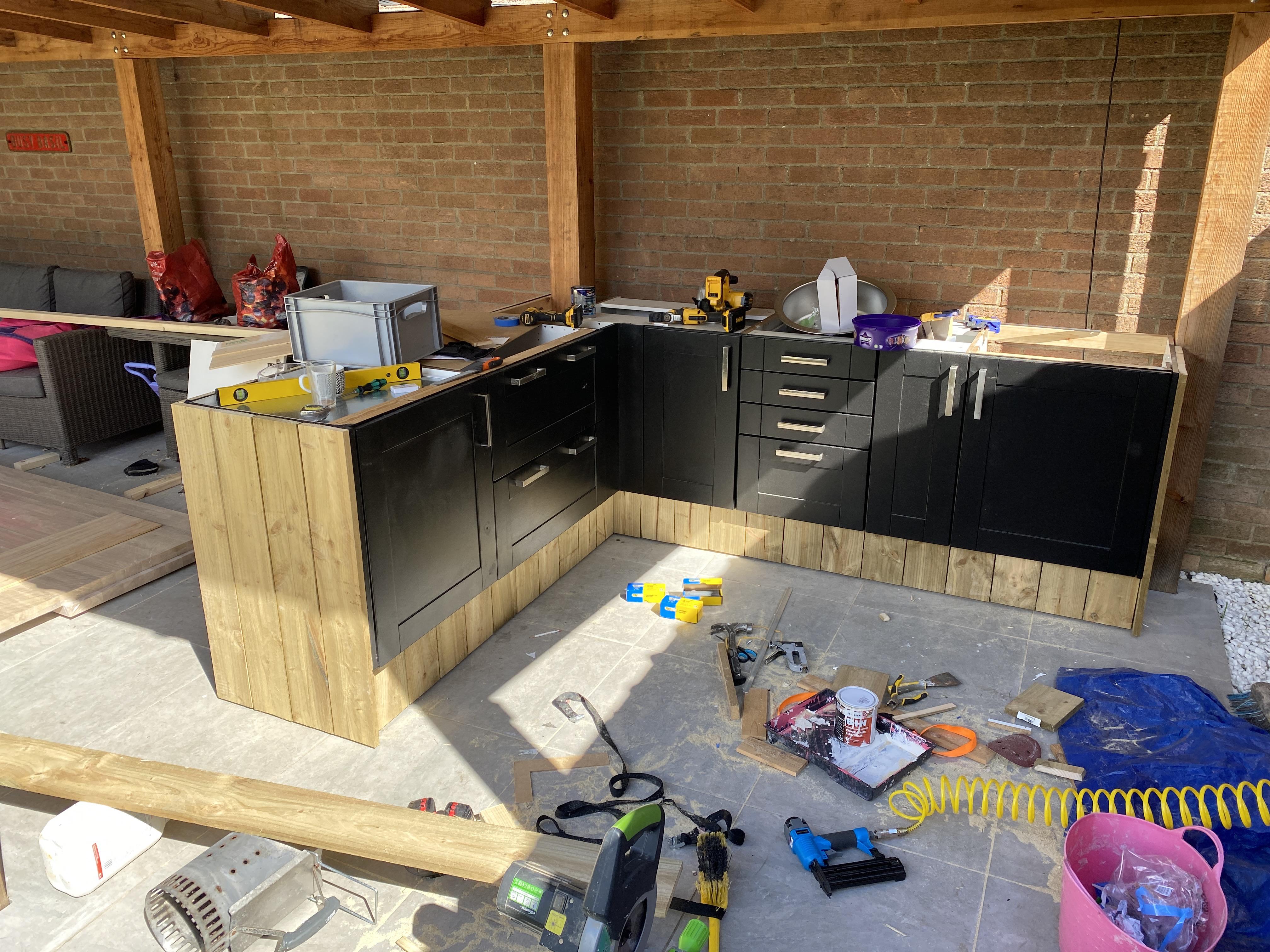
Using Wickes 22x150mm sawn timber again, I clad the cabinets with my 18ga nail gun; I hadn’t yet got my 16ga gun at this point. It would have been better to use the 16ga gun as the 18ga nails were a bit weak for the job.
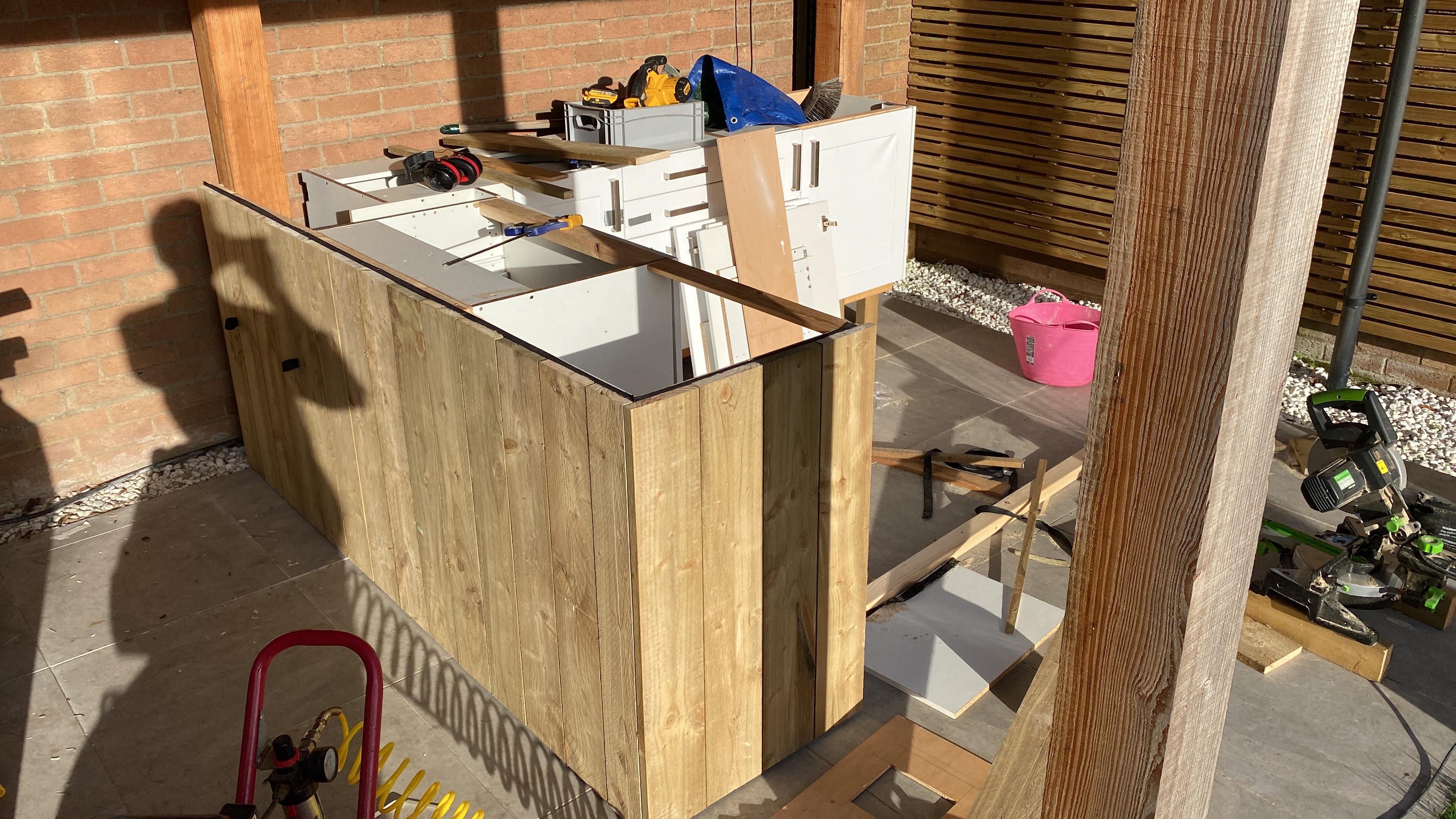
I used packing pieces to ensure a shadow gap between the timbers and also the floor.
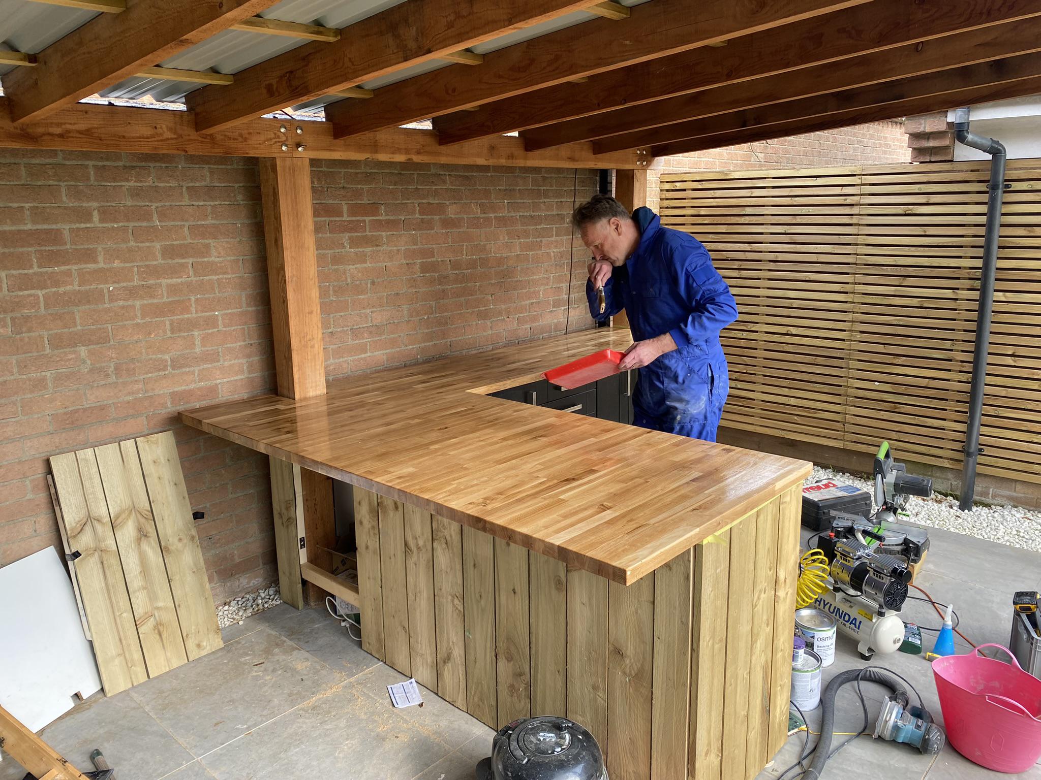
In the above image the timbers look neat! Over the next few weeks they shrunk and warped. This is because Wickes timber was wet. It’s best to let the wood dry first, and to place the timber such that it curves outwards. Fortunately, this is no problem for the rustic look I was going for.
Interestingly, the timber also turned more orange over time, presumably when exposed to UV.
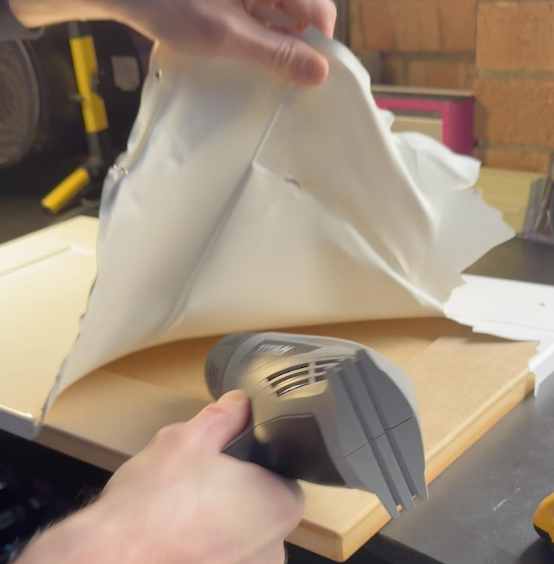
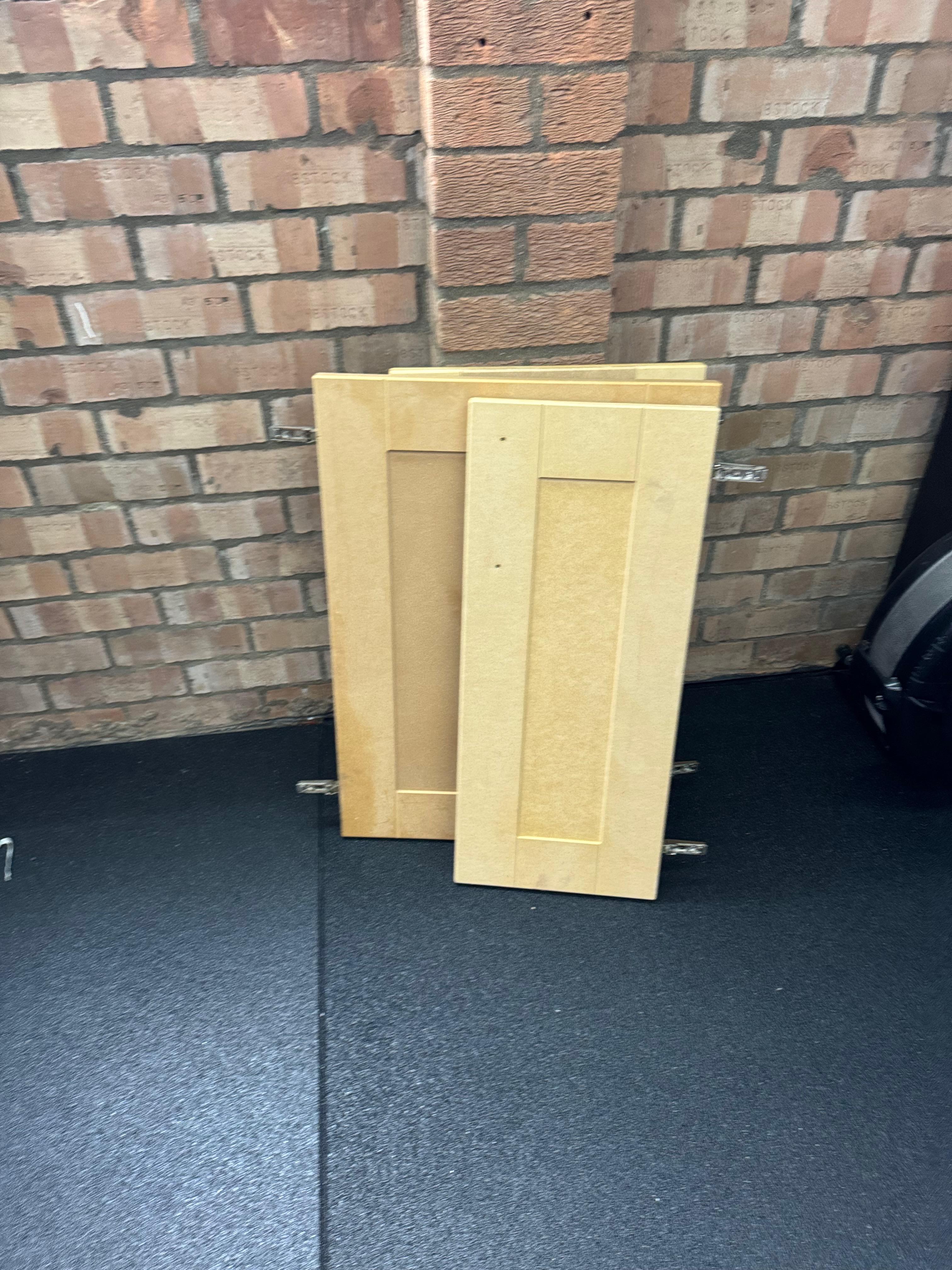
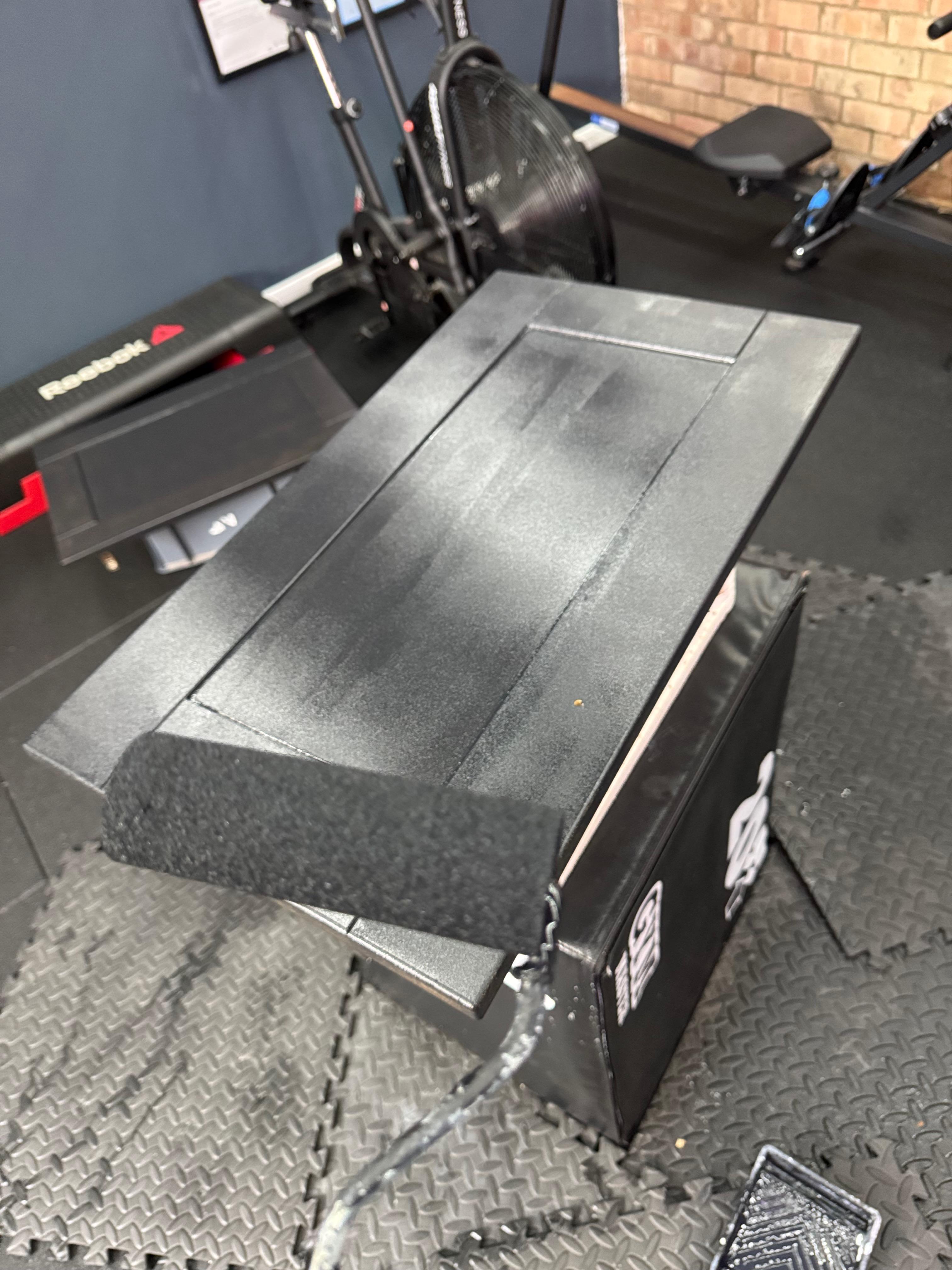
I used a heat gun to strip the horrible white plastic off the doors, and then painted them with some shellac primer and then black garden furniture paint using a foam roller; this left a nice semi-textured finish able to deal with the outdoors despite being made from MDF.
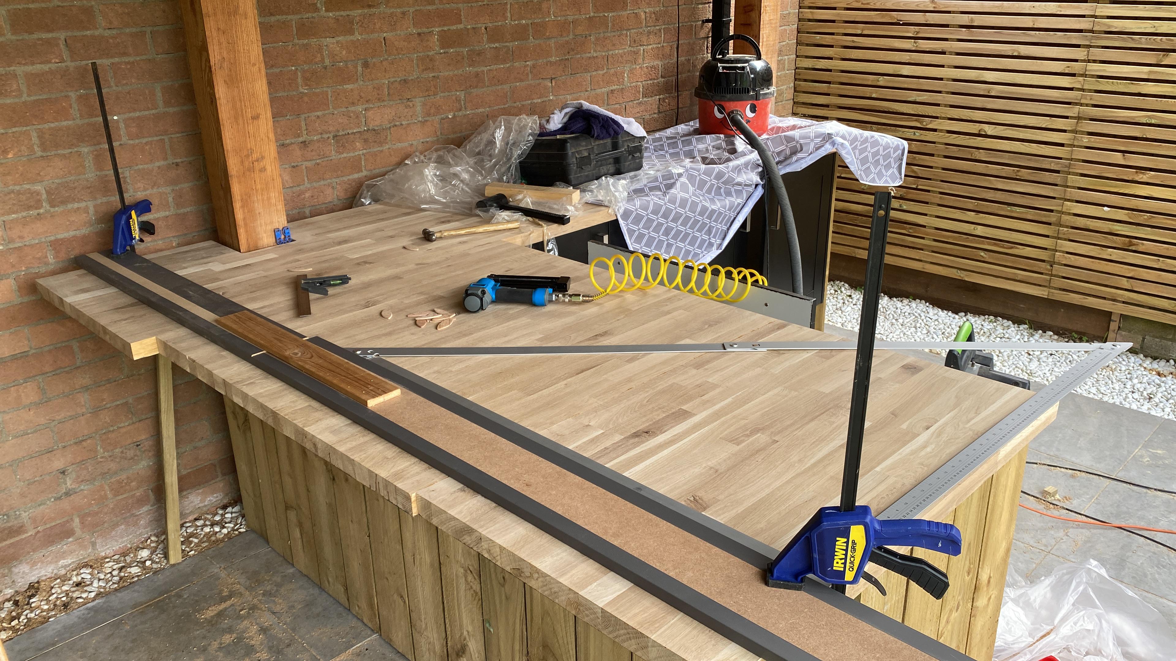
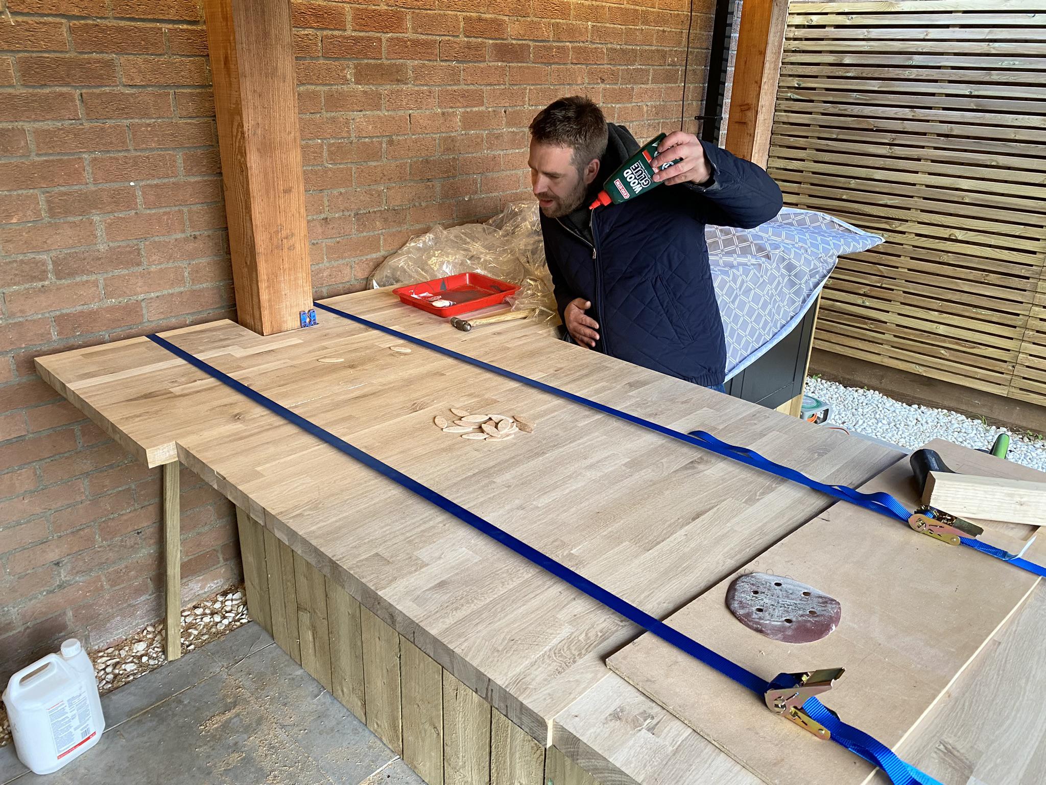
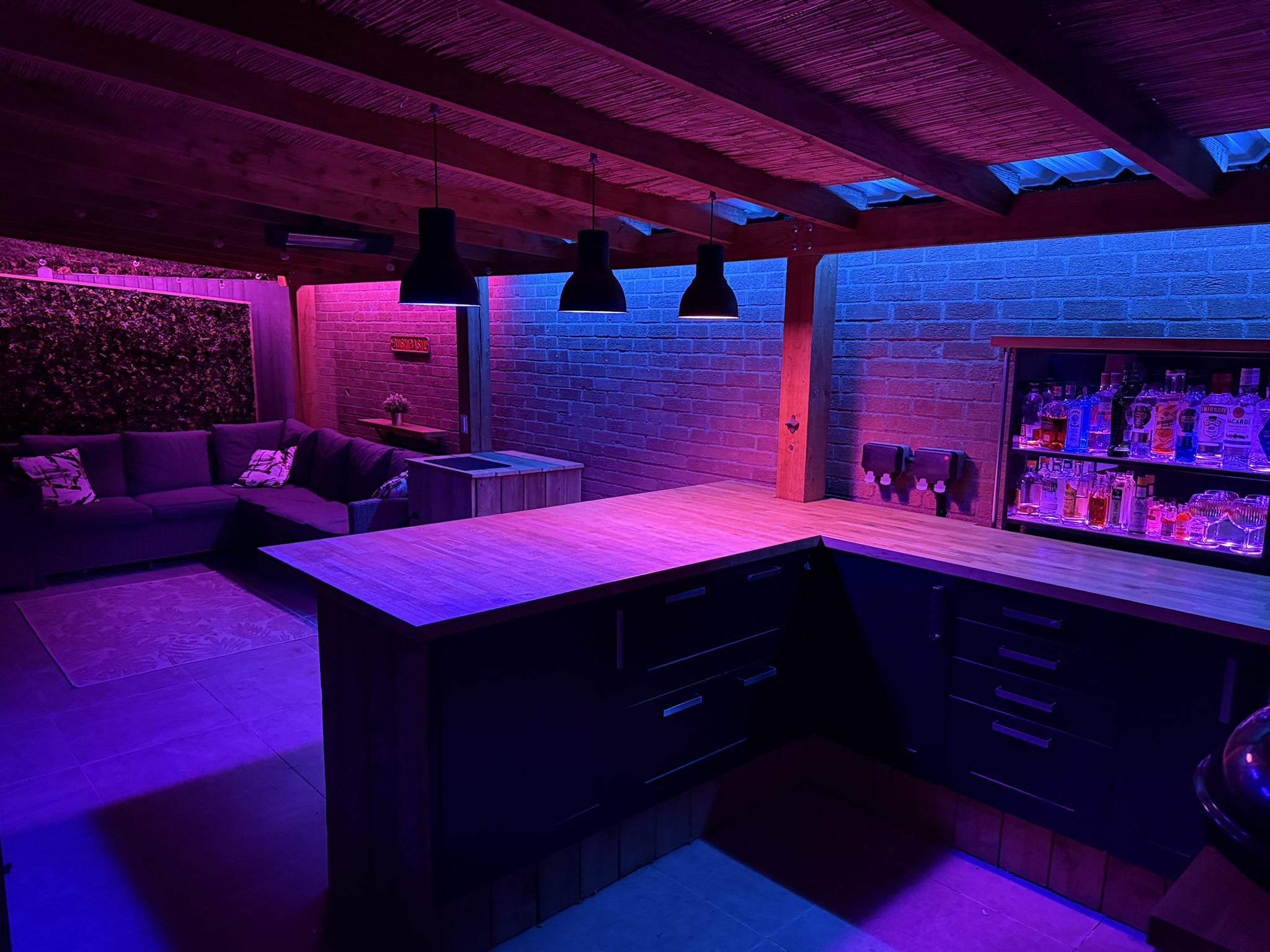
For the worktop I used 40mm thick butcher block. Usually with a corner, you might join end-grain to long-grain with clamps to allow for movement; gluing this would leave to cracking. I wanted something more seamless, so I cut the wider piece into 2 and rotated it such that I could biscuit join and glue long-grain to long-grain.
That way the whole worktop looked like a single piece of wood!
As with most kitchen corners, there was some redundant space behind the cabinets at the back. Given the back is accessible, I figured I may as well use it for the electrical switchgear.
To access the switchgear, I made a secret access panel using spring latches and some straps to allow it to be lifted out.

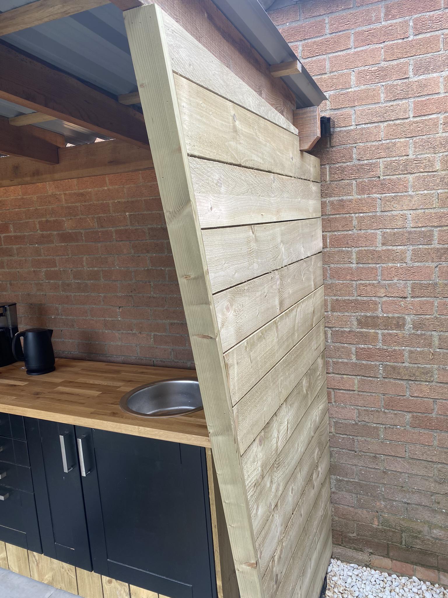
Given the rightmost part of the worktop is near the edge of the structure, it was necessary to protect it from rain. I made a simple angled rain guard from the same timber as the rest of the bar, screwed and nailed into place. It is angled such that it starts thin on the ground and gets thicker towards the top – this proved to be a good choice as the worktop never gets wet and the guard looks like an intentional part of the structure.
Frame
2021
Lessons learnt
- Don’t use green wood (maybe)
- Double check your wood (and order) as received
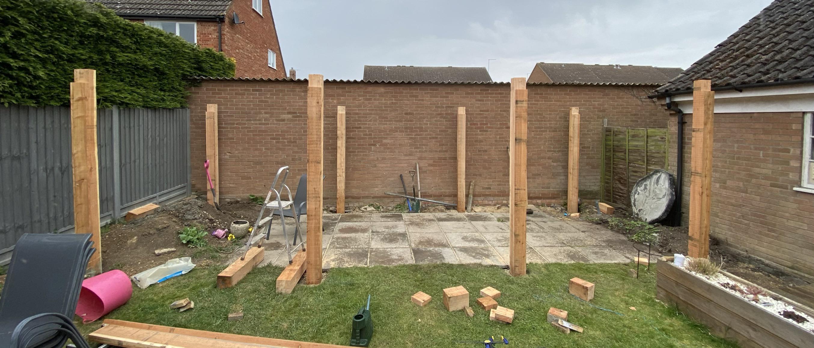
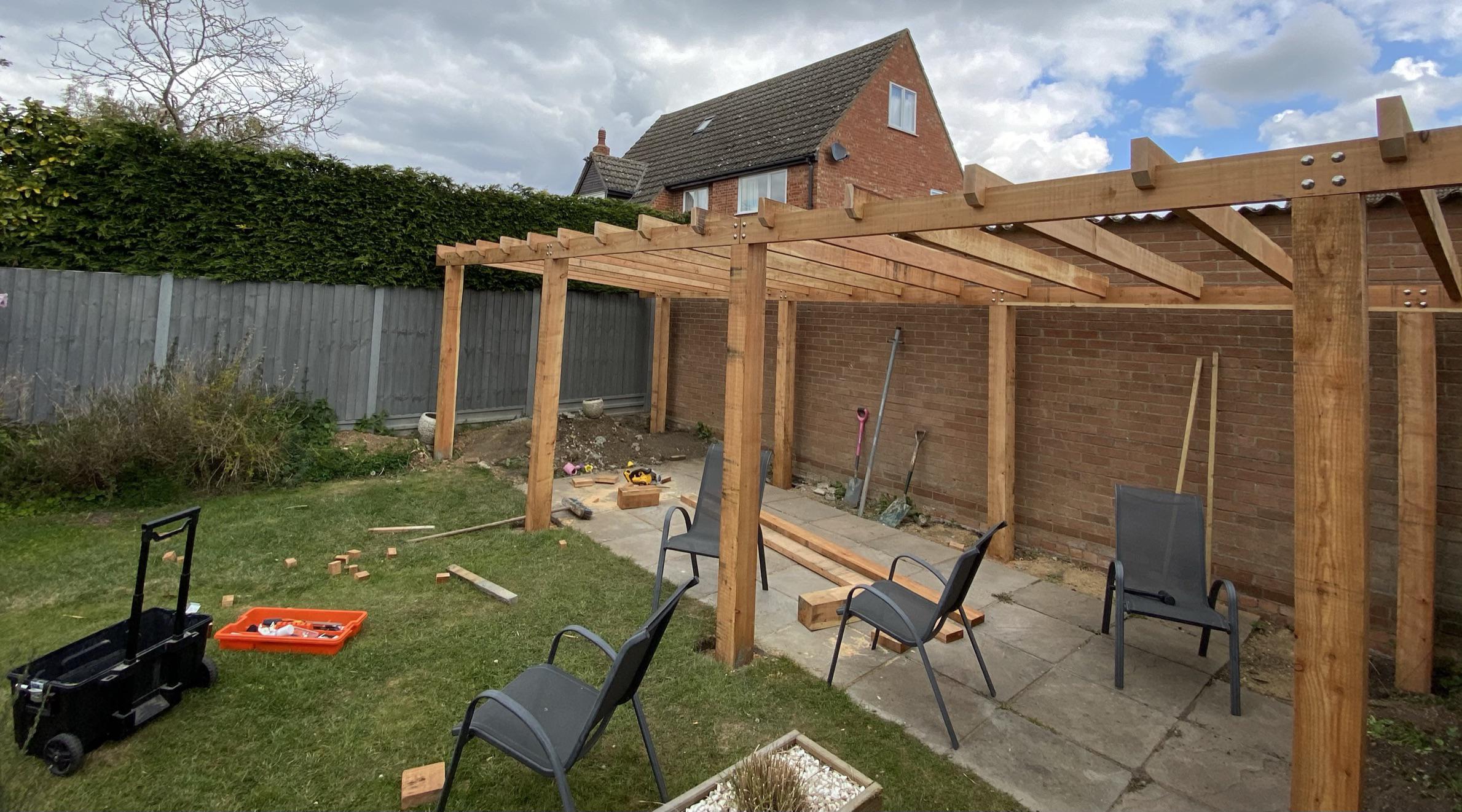
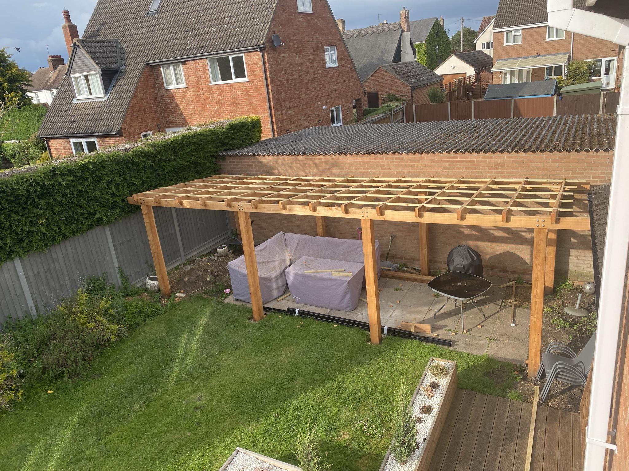
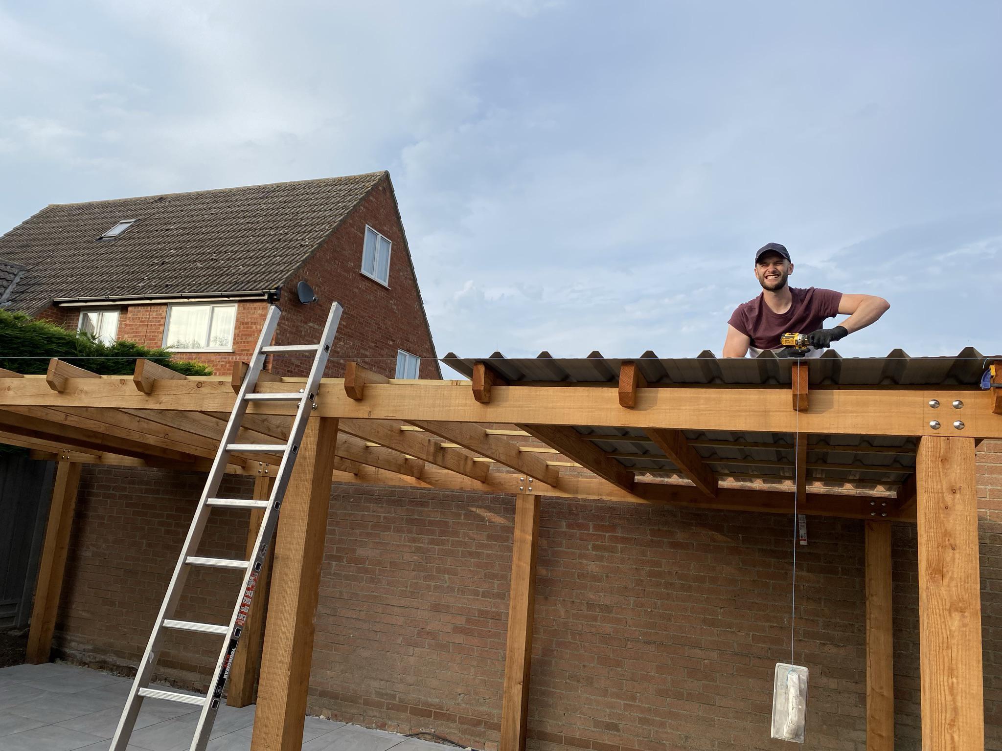
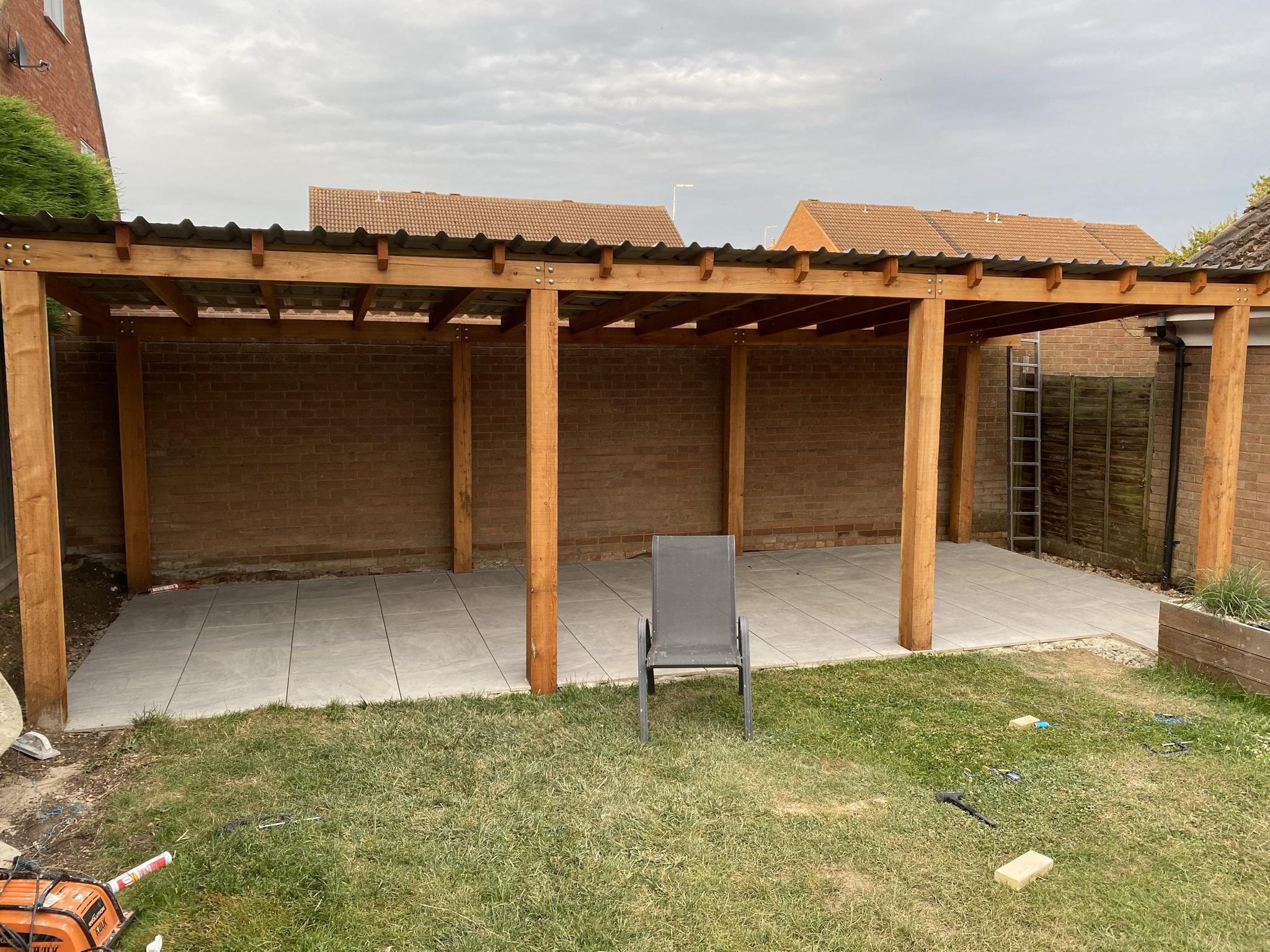
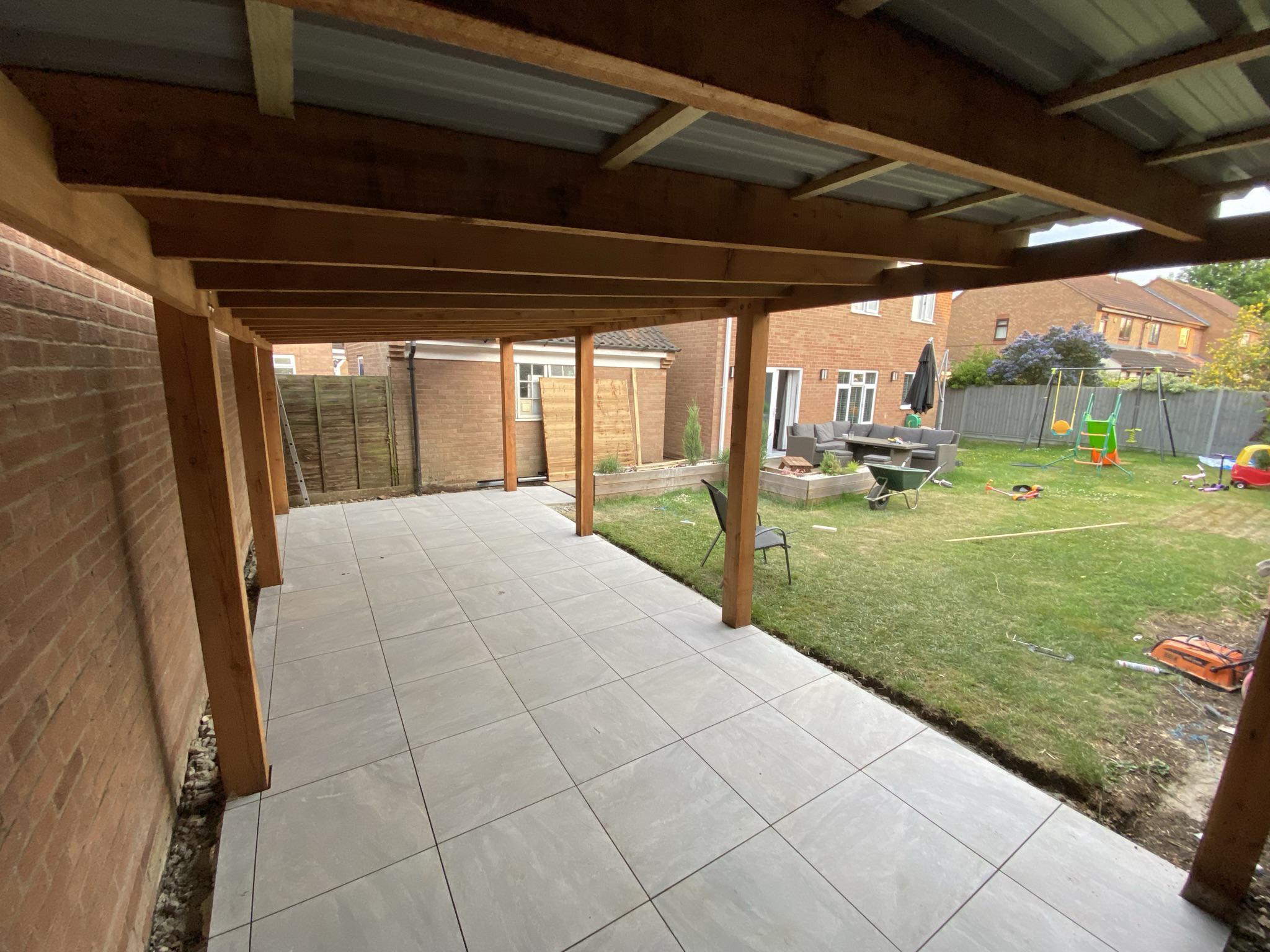
Now for the biggest part of the project – the frame. My brother designed the frame, comprised to be robust and to last at least 20 years. It’s comprised of 8x 150mm posts, with a pergola style roof.
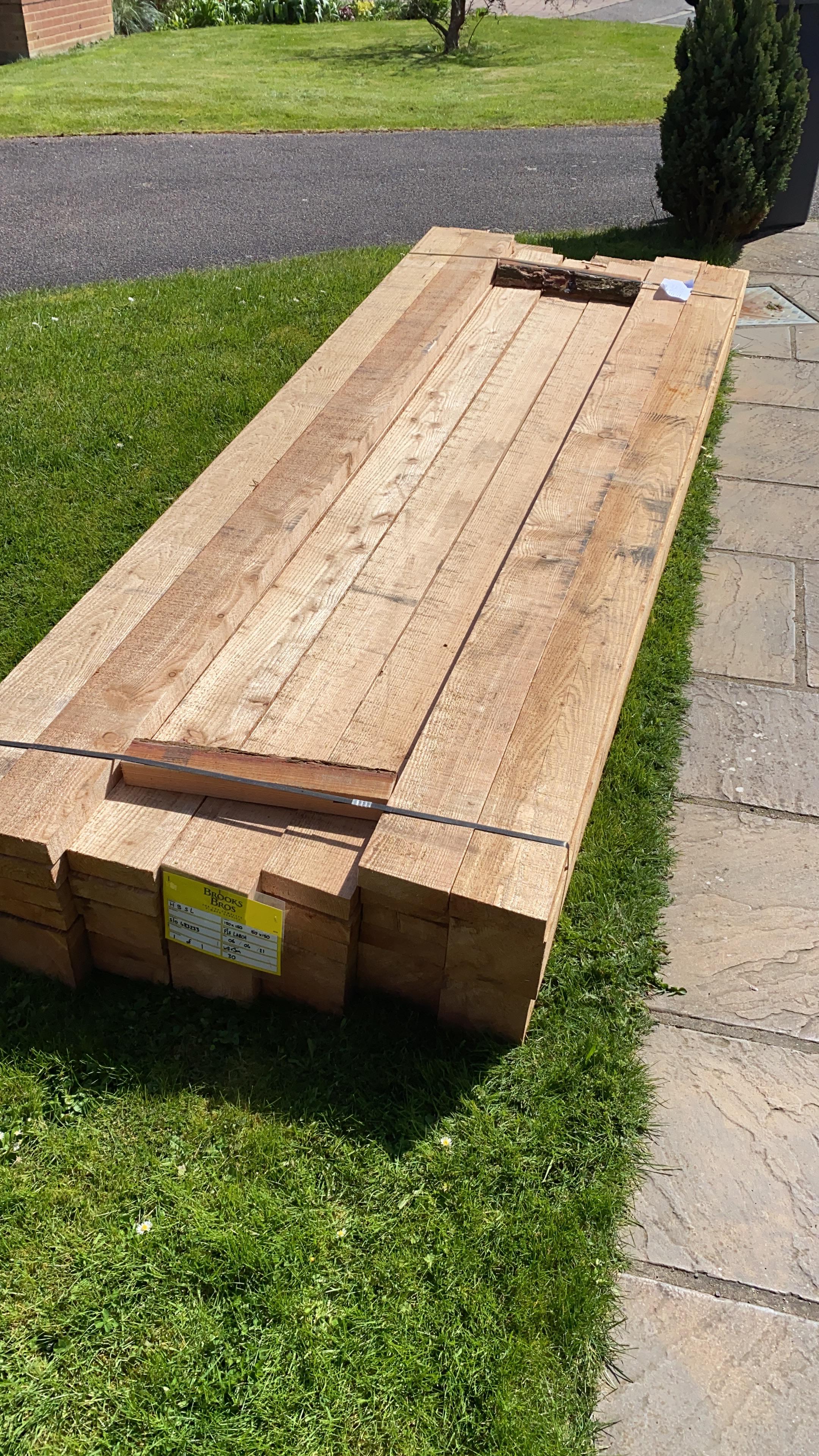
The first mistake was receiving the wrong length of wood. I had ordered 3.6m lengths, but I was quoted for 3.0m lengths and I didn’t notice until construction. Make sure you double check your order and delivery!
I had also ordered “green” (Larch) wood, which is wood that hasn’t been dried or treated. As a result it can shrink and warp. If I was doing this again I would use dried and treated wood, though it didn’t matter too due to the rustic aesthetic.
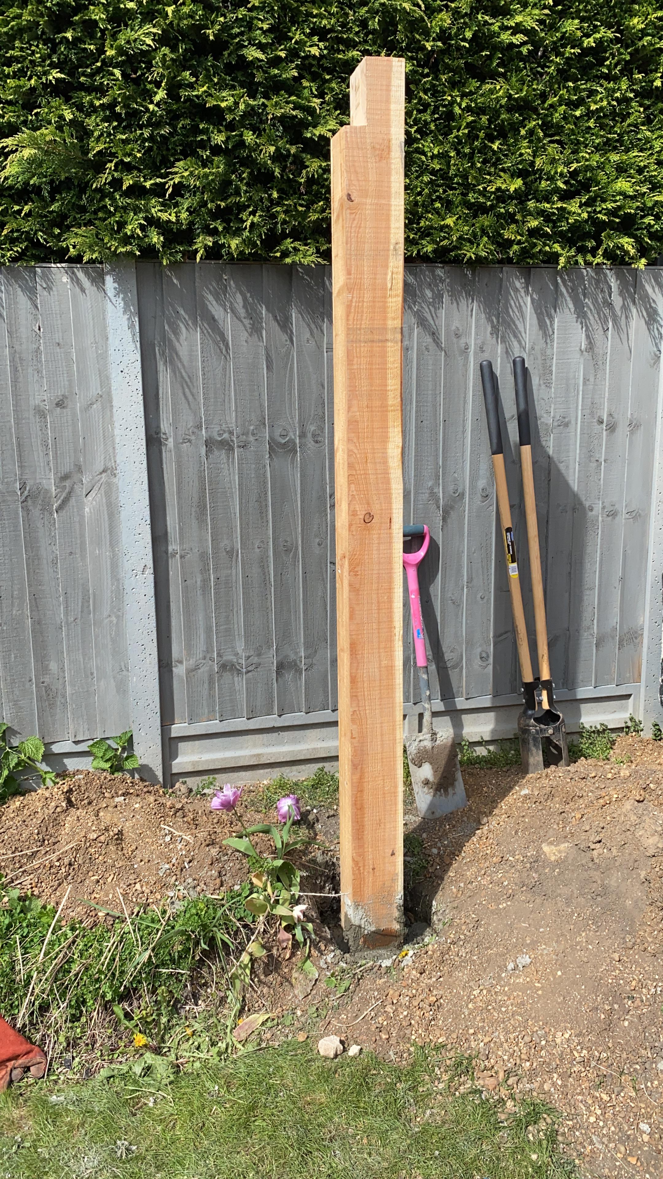
With the help of my Dad and Brother, we dug the holes with a post digger, and concreted in the posts with 4:1 sharp sand and cement. 6:1 may have been better, 4:1 was likely excessive. We also dug about 800mm deep, which is again probably excessive.
We mixed by hand too! A cement mixer would have been better, and is definitely worth the rental; when we did the floor later on we did so.
We used a laser line with a tripod to ensure the posts were all aligned, together with some string.
Building this again, I would have used some meta shoes to hold the posts in place to keep them from the ground where they could rot. Though, after almost 4 years they don’t show any signs of rot and are still solid as they don’t spend much time wet.
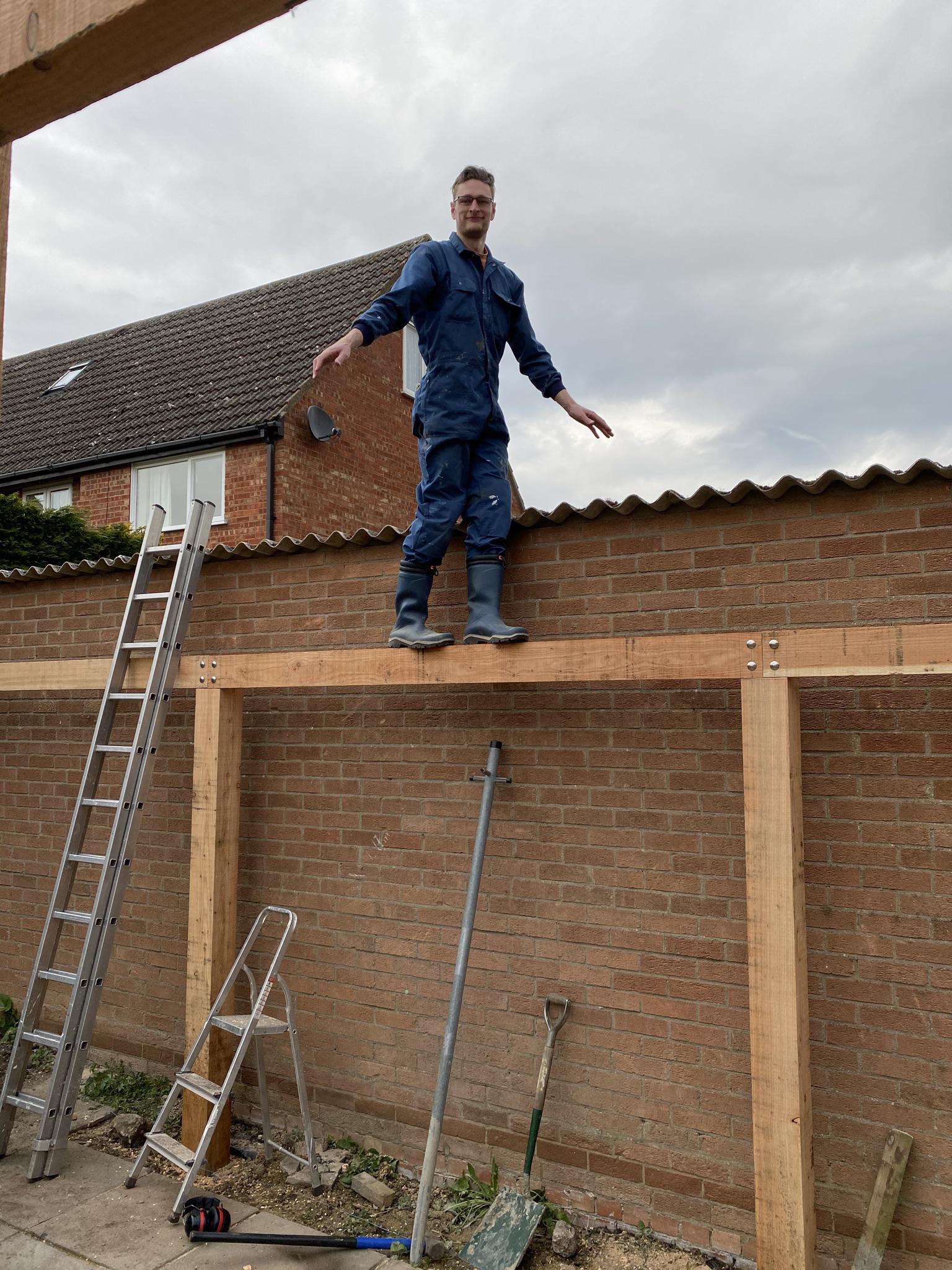
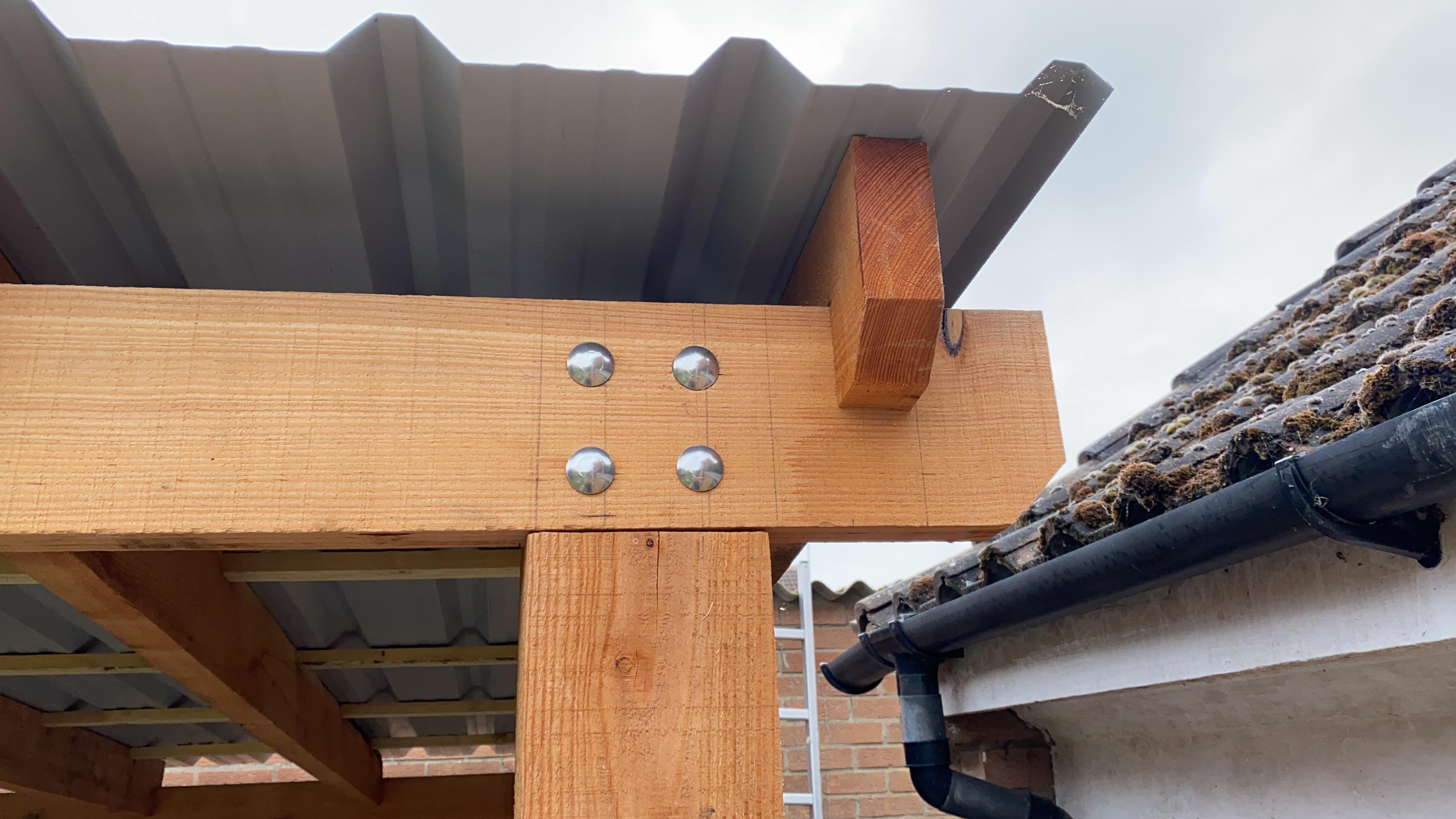
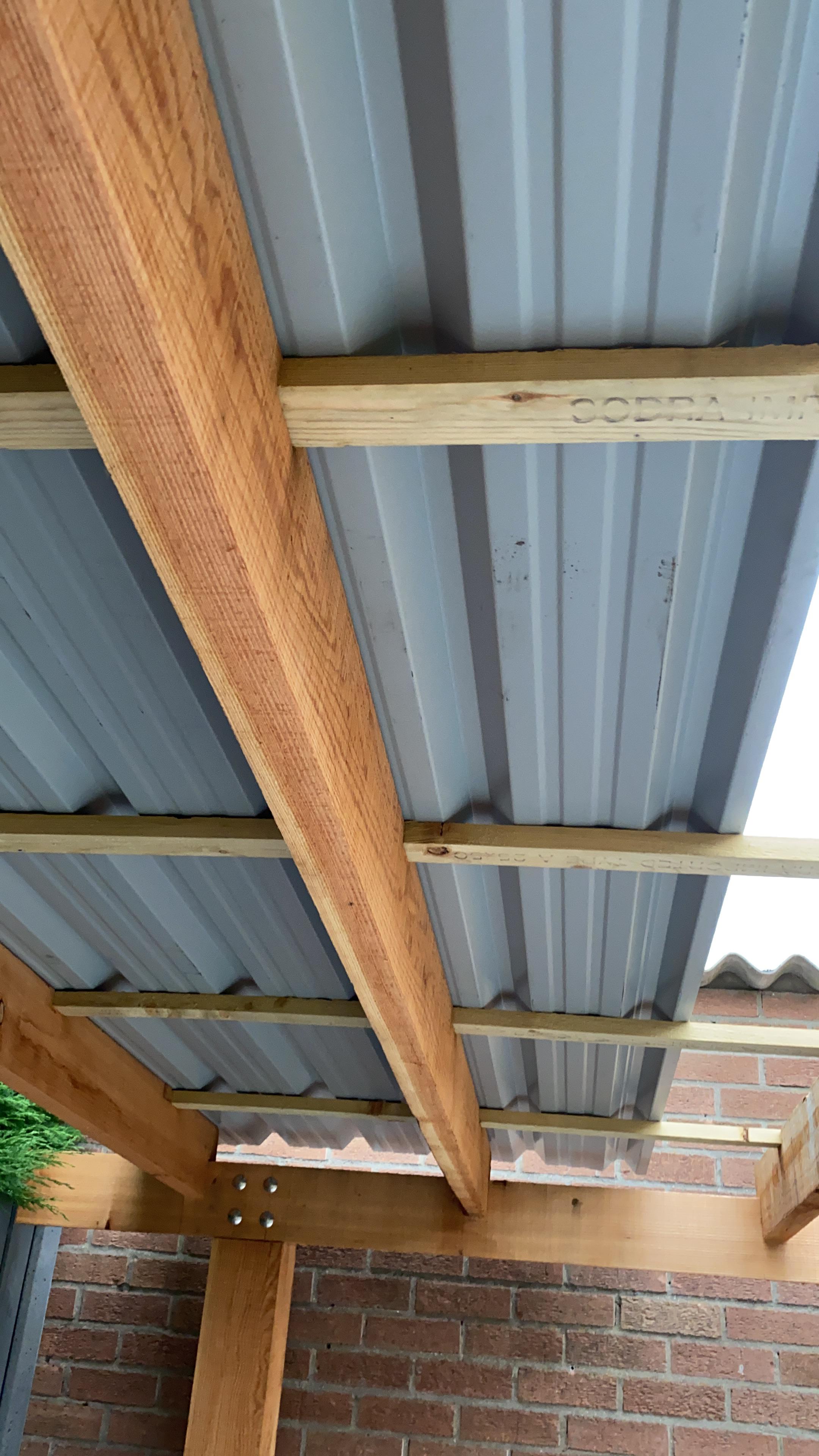
We installed the beams next, with a lap join on each post. We used stainless steel coach bolts to hold them in place, which looked great won’t stain the wood. I would have used thicker beams, possibly the same 150x150m, posts instead for better balance – despite this being more than strong enough.
All cuts and joins were made with a battery powered circular saw, an investment I made for this build and haven’t regretted.
A year later, the beams had bent a bit. I should have aligned them so the grain pattern was consistent so they all curved downwards; however it’s only noticeable if pointed out.
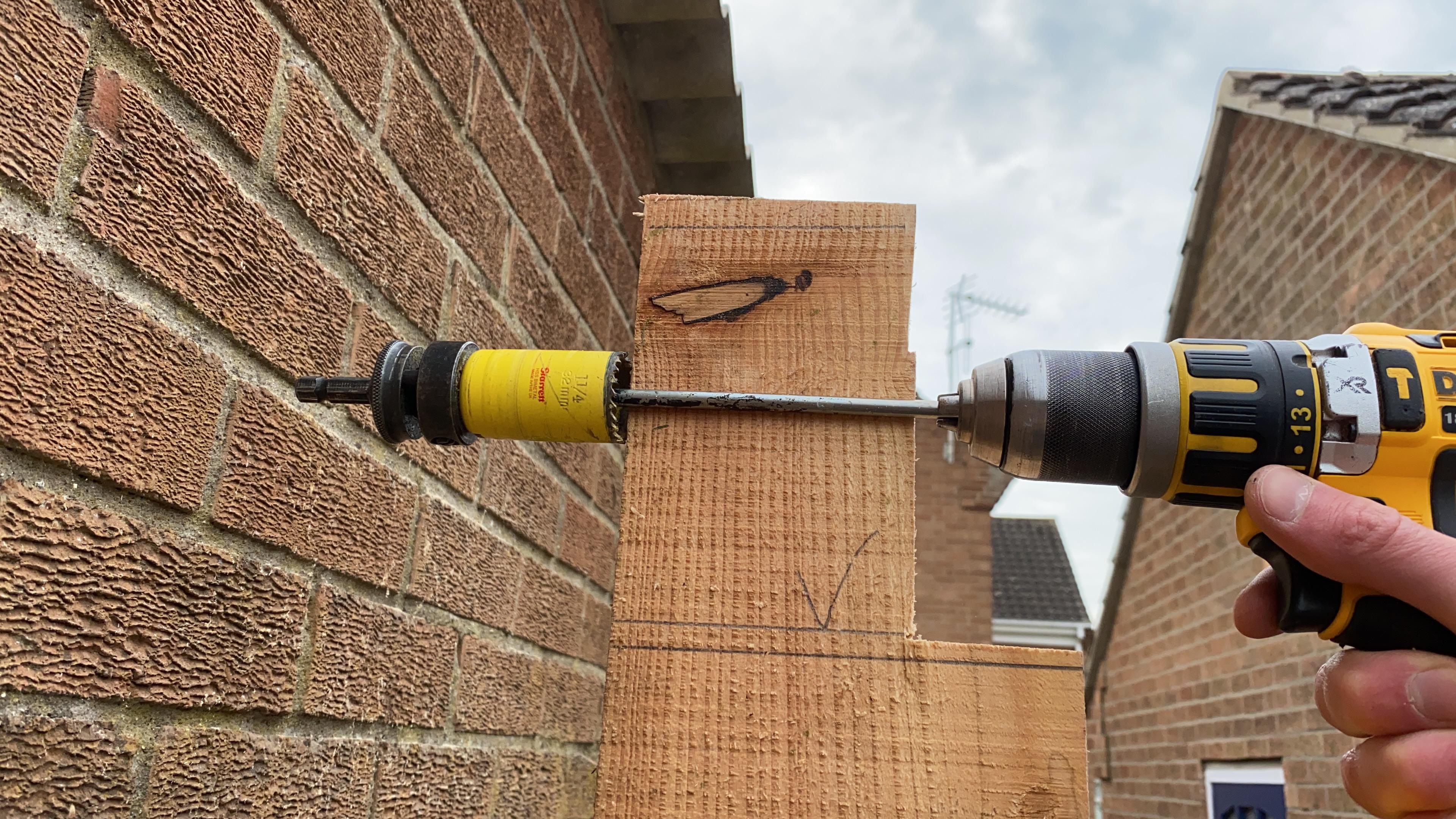
For the rear posts I realised late that I’d need to drill some holes from the rear to accept the coach bolts. I couldn’t remove the posts of course, so I used a metal bar to drill in reverse. It worked great but my battery drill didn’t like this and started to smoke! It was surprisingly OK though, after I let it cool.
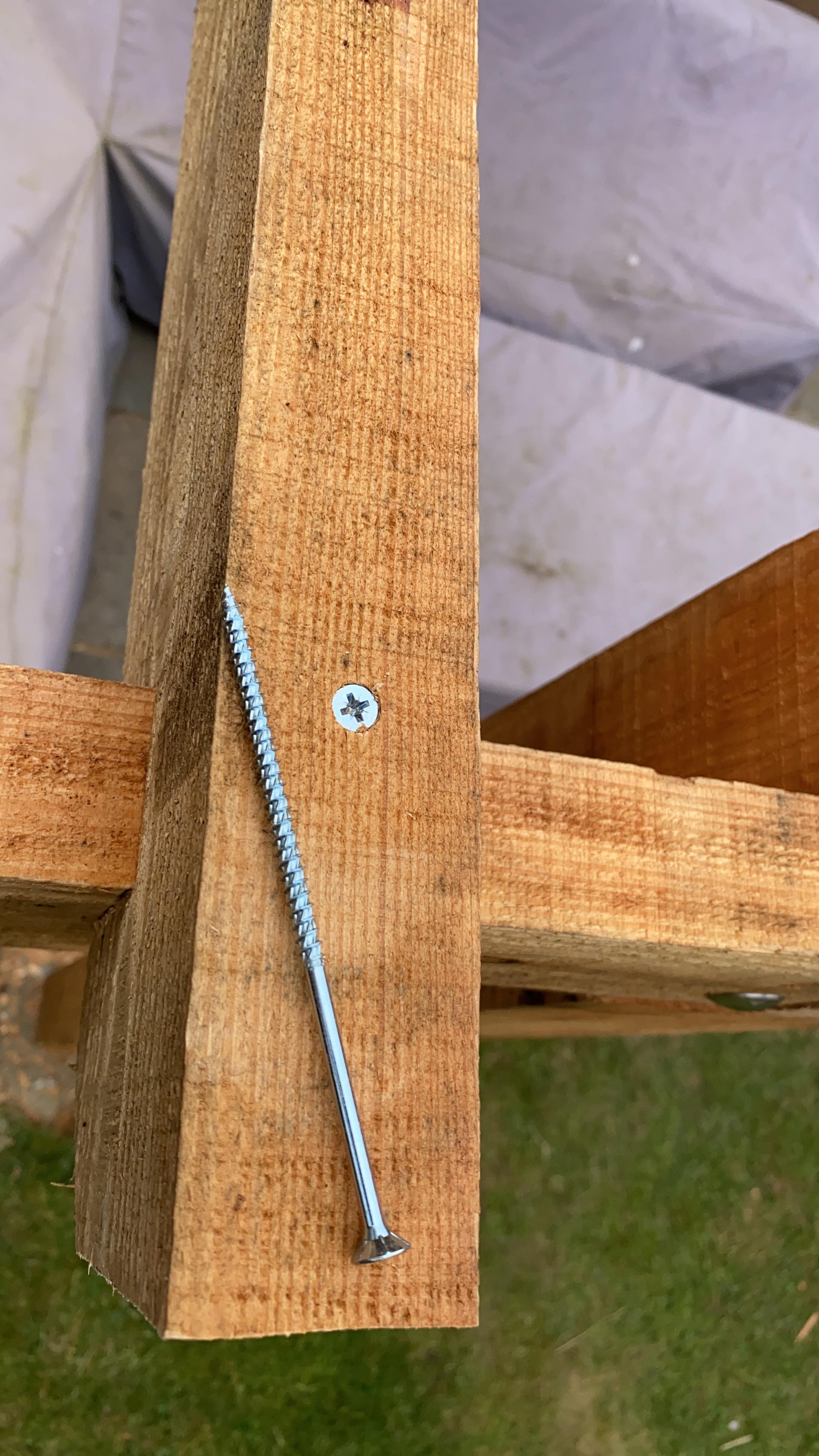
The top beams were installed next, again with lap joins, and screwed in place.
Roof
2021
Lessons learnt
- Don’t get a black roof
- Don’t use plywood to line the roof
- Maybe use 1200mm spacing
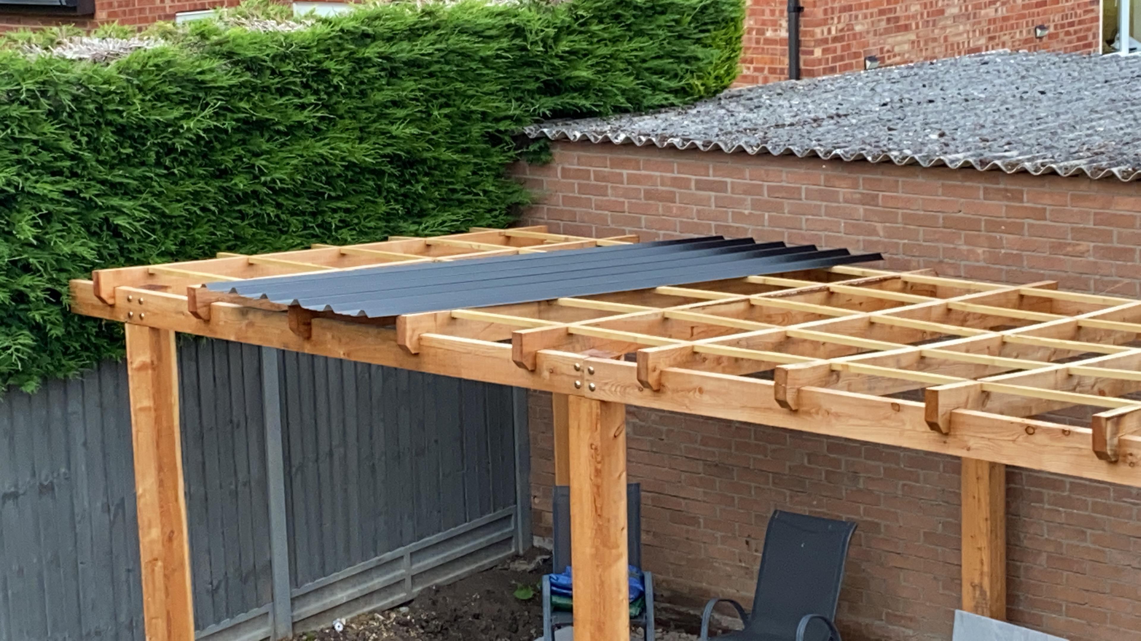
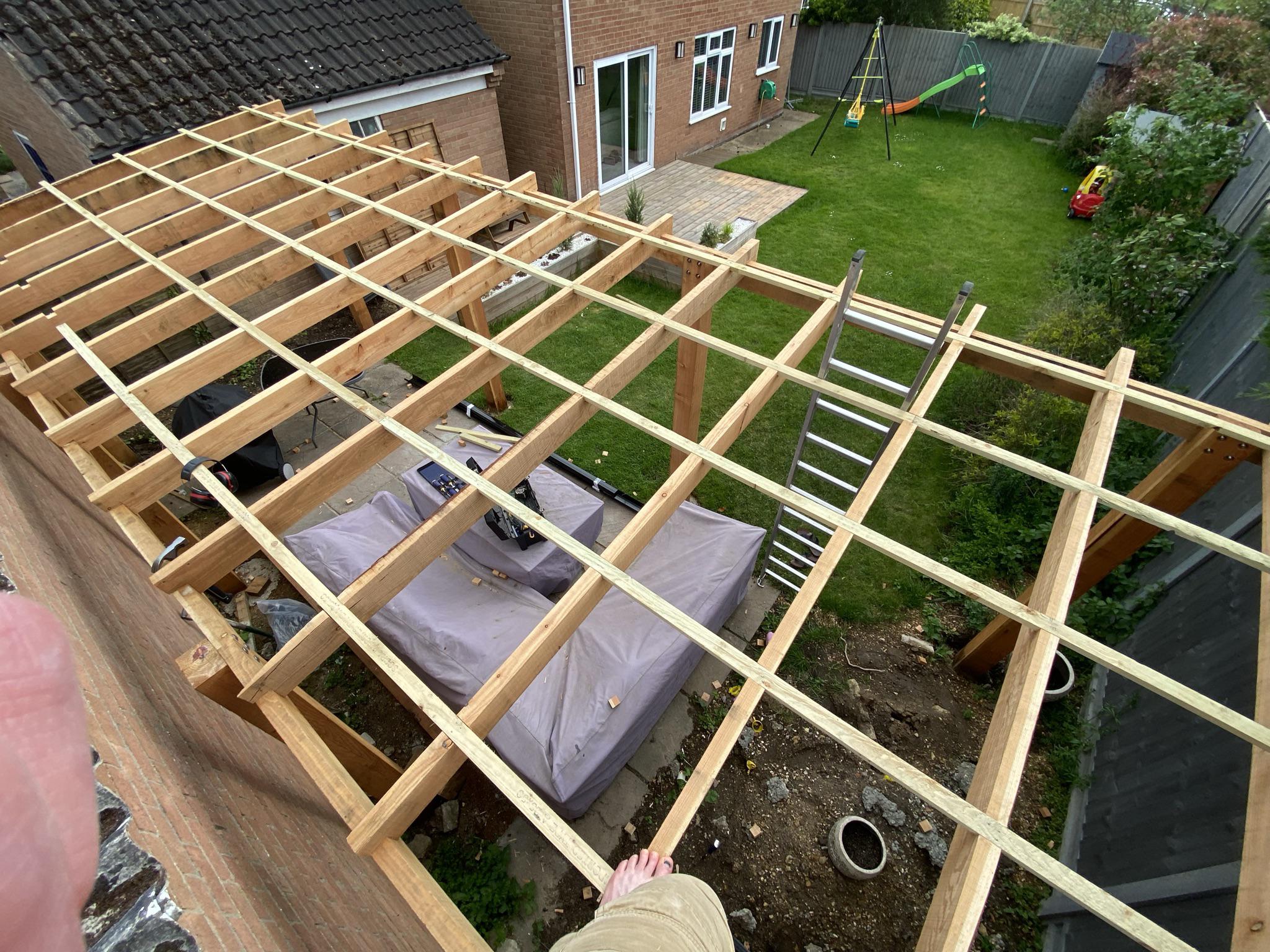
I installed some 22x50mm purlins across the top, rebated into place using a circular saw an chisel. The purlins were spaced at 600mm centres, just like the top beams. I used some string to line up where to cut.
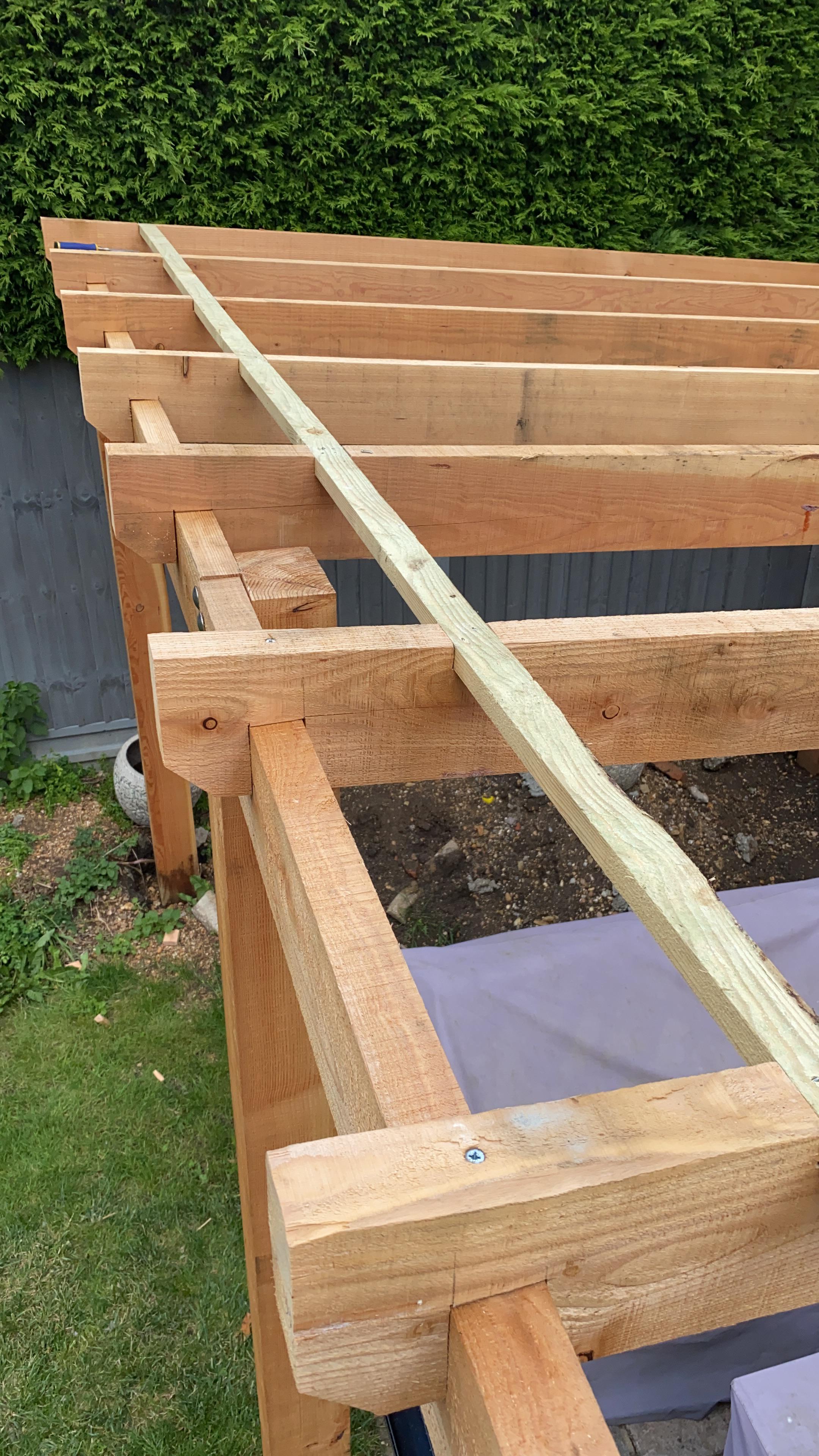
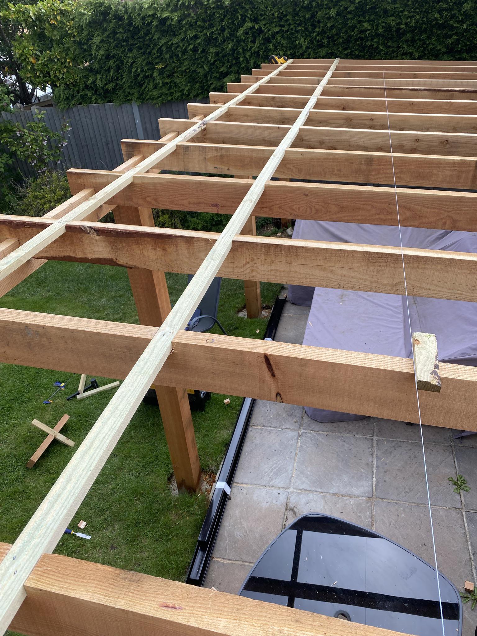
I think it’s more conventional not to rebate the purlins, and to use wider wood. I’m happy with what I did – it’s strong enough due to the 600mm top beam spacing.
For the roof covering I chose 1.5mm aluminium roofing sheets in black. Black was a mistake! It absorbs the heat from the sun and radiates it back downwards. This was later a problem I wasted a fair bit of time and money trying to solve.
I fit a gutter to the rear, using flashing tape to direct the water for when there’s a lot of rain. I have to admit I printed some parametric gutter interposers to get the roof to align to the gutter, as the roof was slightly at an angle relative to the wall, where the clips were fitted.
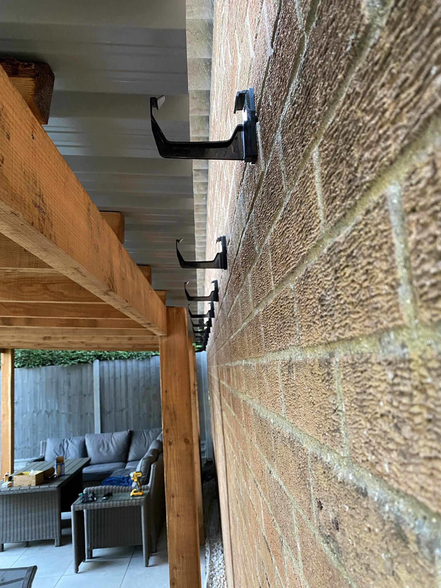
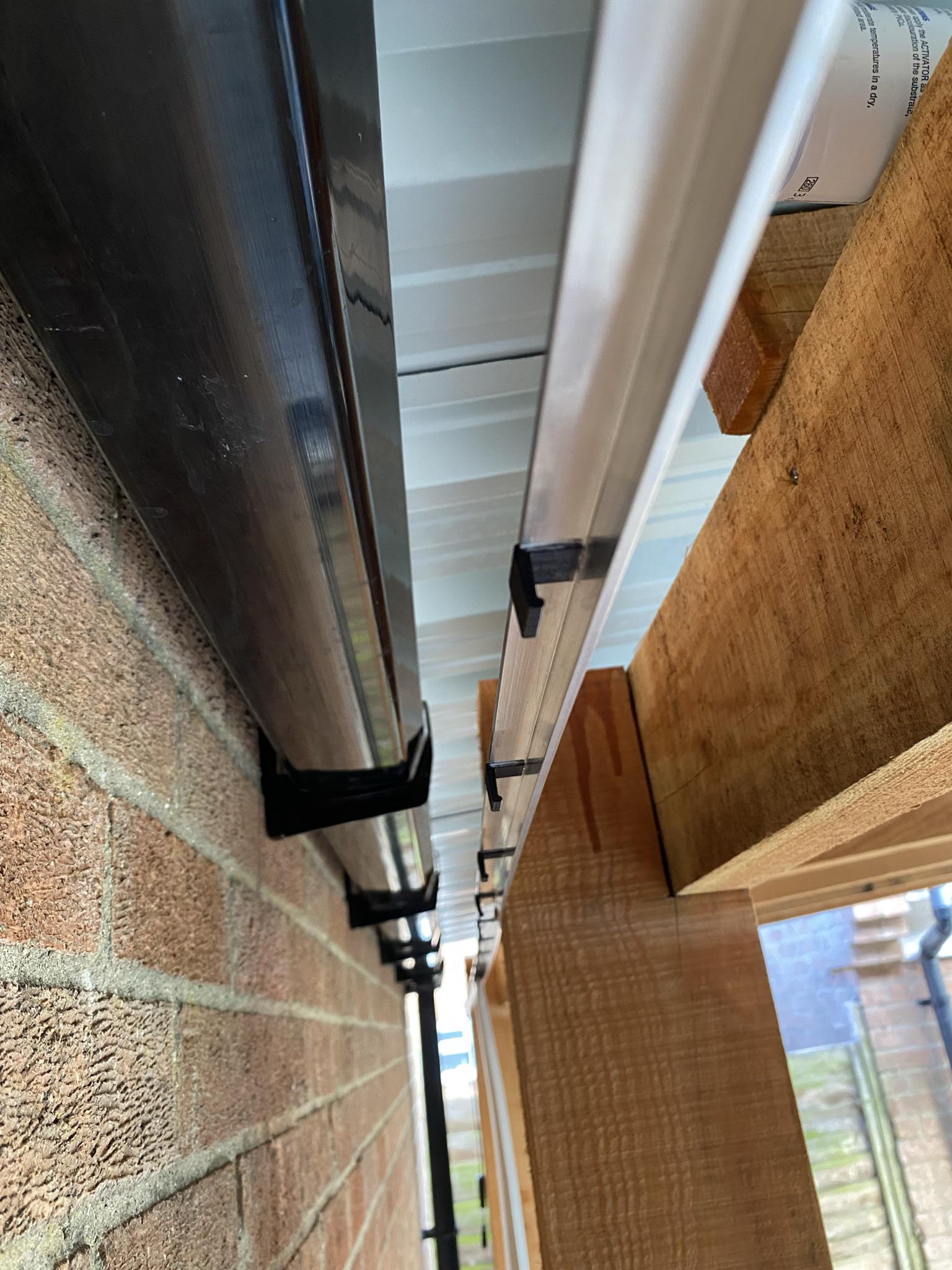
I also had to add a gutter brush to prevent driving rain entering via the gutter.
Back to the heat problem – I tried adding some metalised bubble wrap to the roof, lined with 3mm plywood to protect it. It seemed to work well, but I was never happy with the finish – due to the warped nature of the top beams, and not scribing in each panel, it looked a messy.
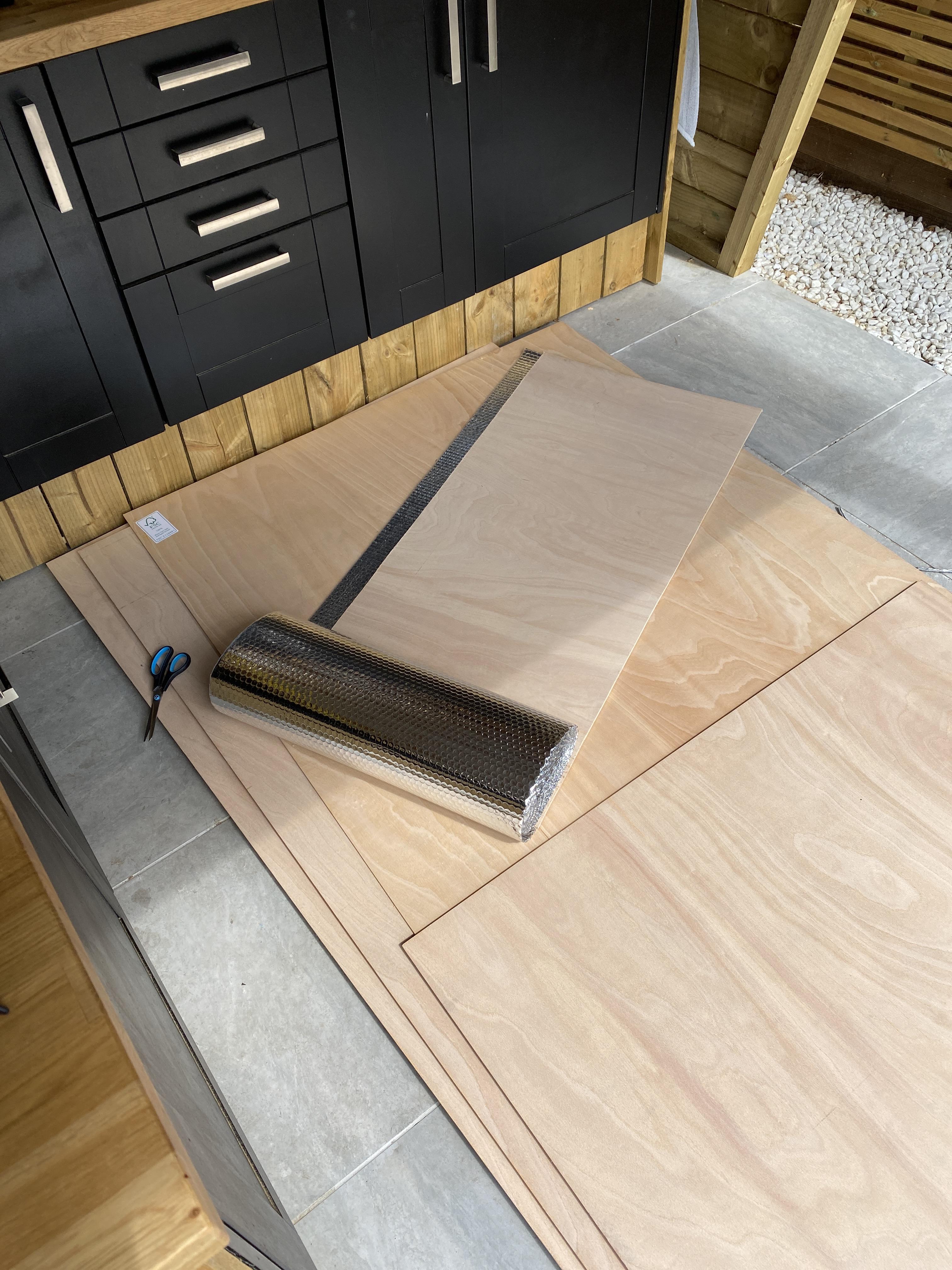
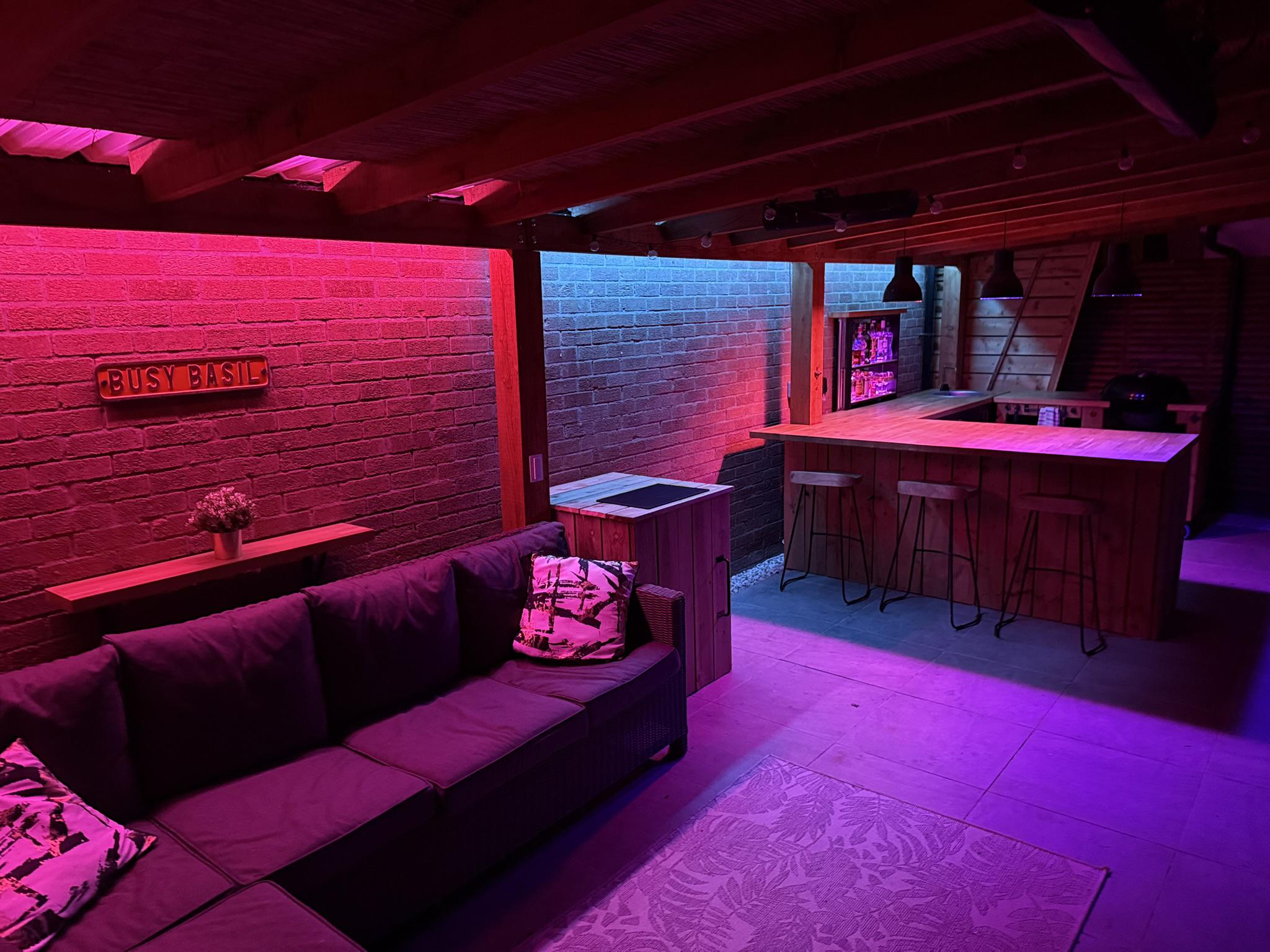
The plywood got mouldy during the winter too, so I removed it. Eventually I decided to cut up bamboo fencing and staple it to the roof purlins. This worked great, and looks OK too – several people have said it makes them feel like they’re on holiday in a tiki bar!
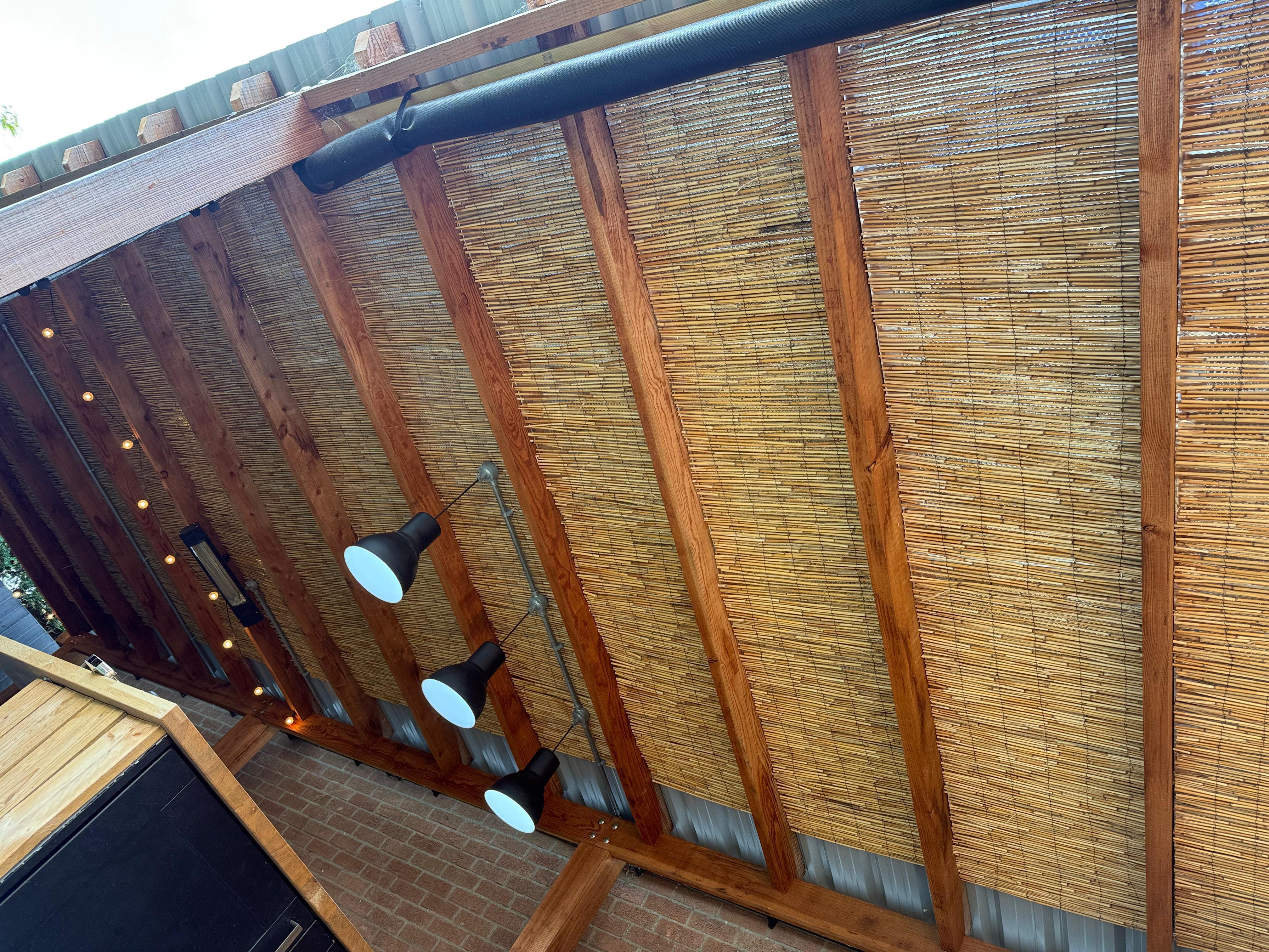
To cut the bamboo, I settled on a pair of secateurs – nothing else really worked well. I stapled the bamboo to the purlins using a heavy duty staple gun.
Visor, sign and mesh
2023
Lessons learnt
- Use ABS filament for outdoor signs
- Nail the letters to the sign
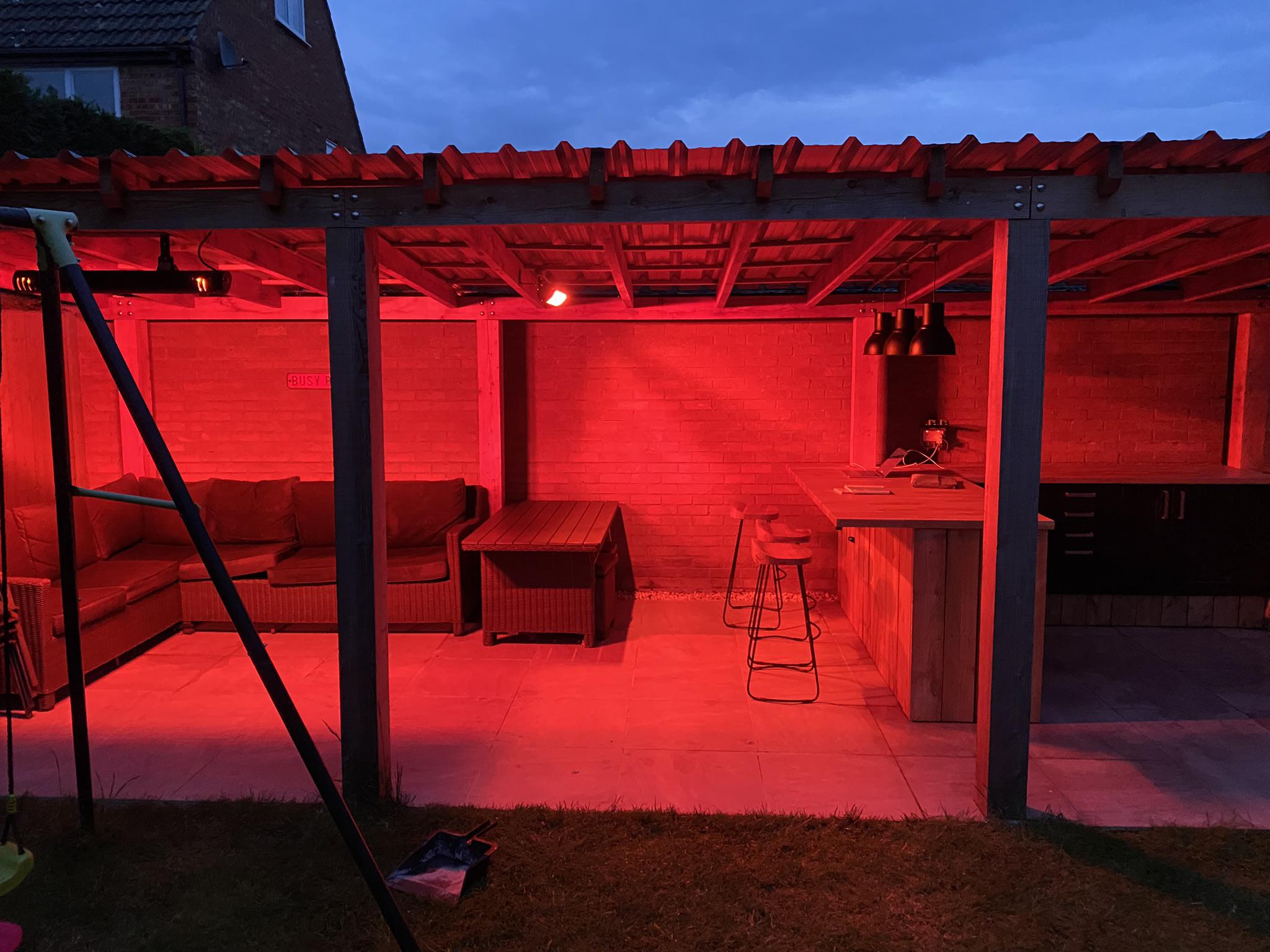
The 3 p.m. sun was too bright and hot, so I added a visor to the front. Like the rain protectors, I used 50x50mm timber to construct a frame and cladded it in the same 22x150mm timber as the rest of the bar. This was enough to block the sun from the seating area.
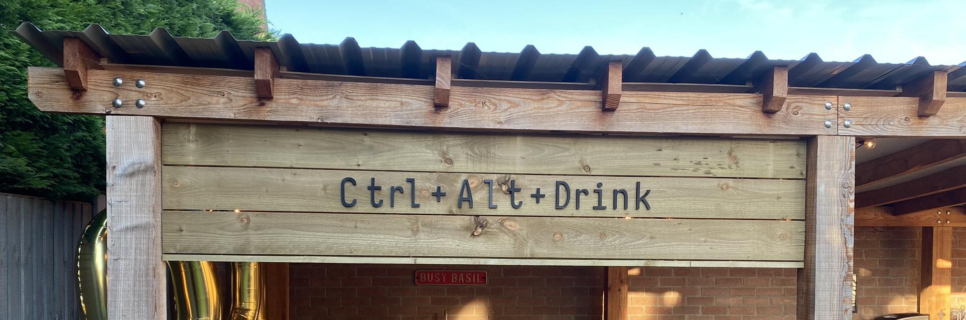
I then printed the name in PLA, and Blu-Tacked it to the front. This worked fine until it got hot – the letters fell off and also warped!
Re-printing in ABS fixed the warping, and drilling holes to insert panel nails stopped the letters from falling off. I would have added regular perforations to support nails if I was to do it again.
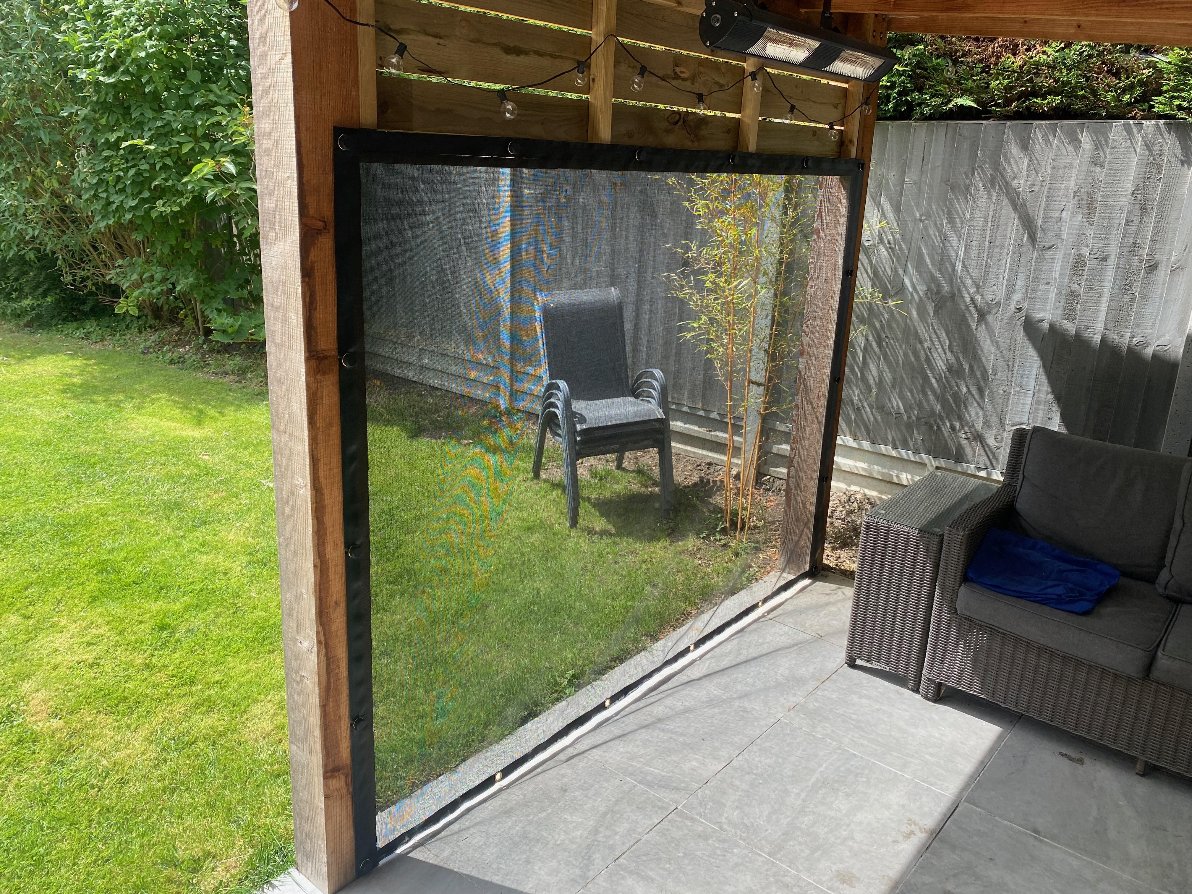
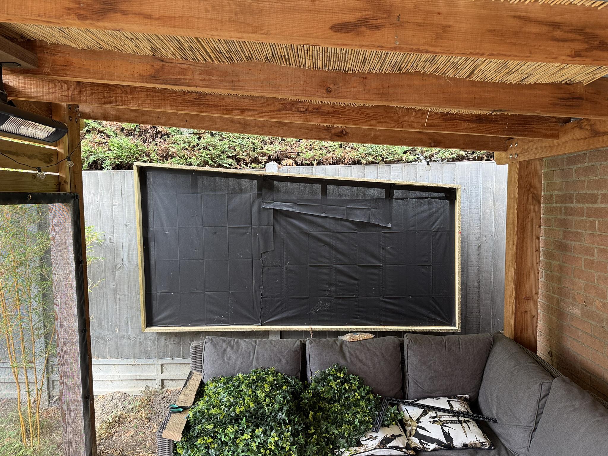
To further mitigate the sun, I added some black mesh tarpaulin below the visor. This helped a lot – so I also added the same to the other front sections.
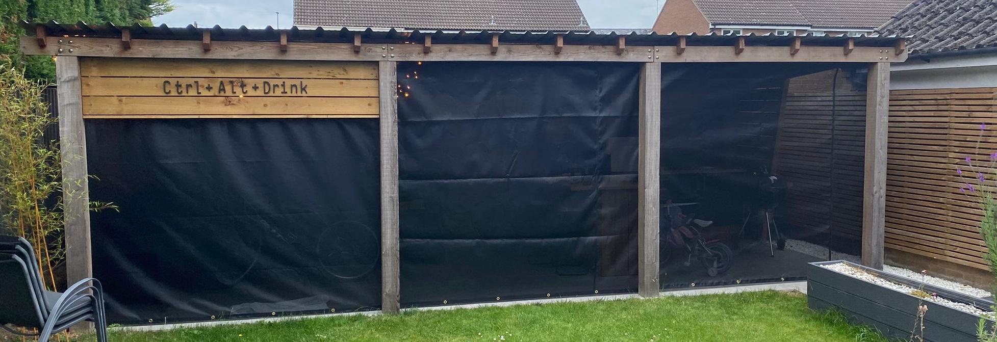
I only put the mesh on the other sections during the winter – it stops the driving rain from getting the worktop wet, making it unnecessary to cover for protection.
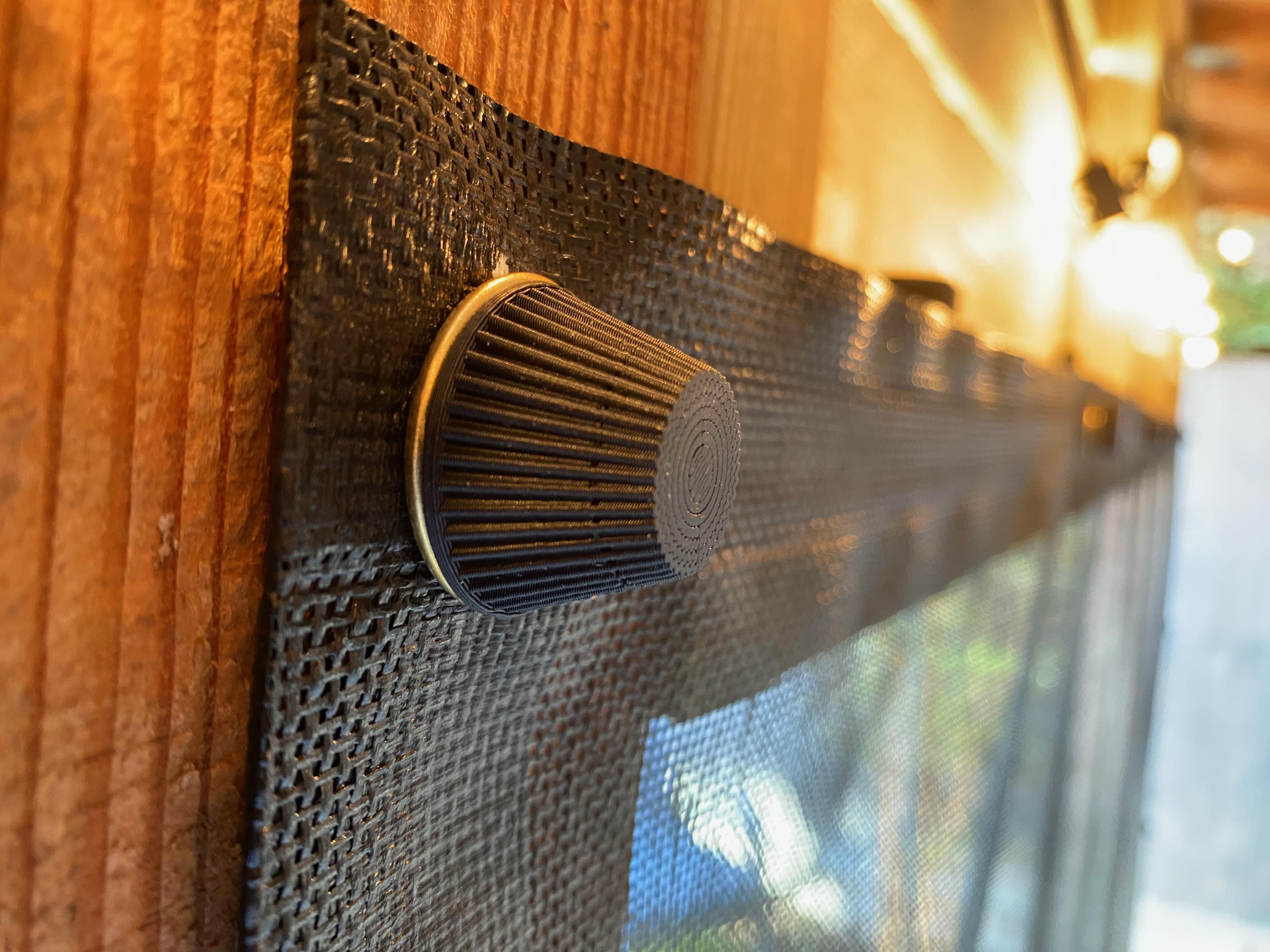
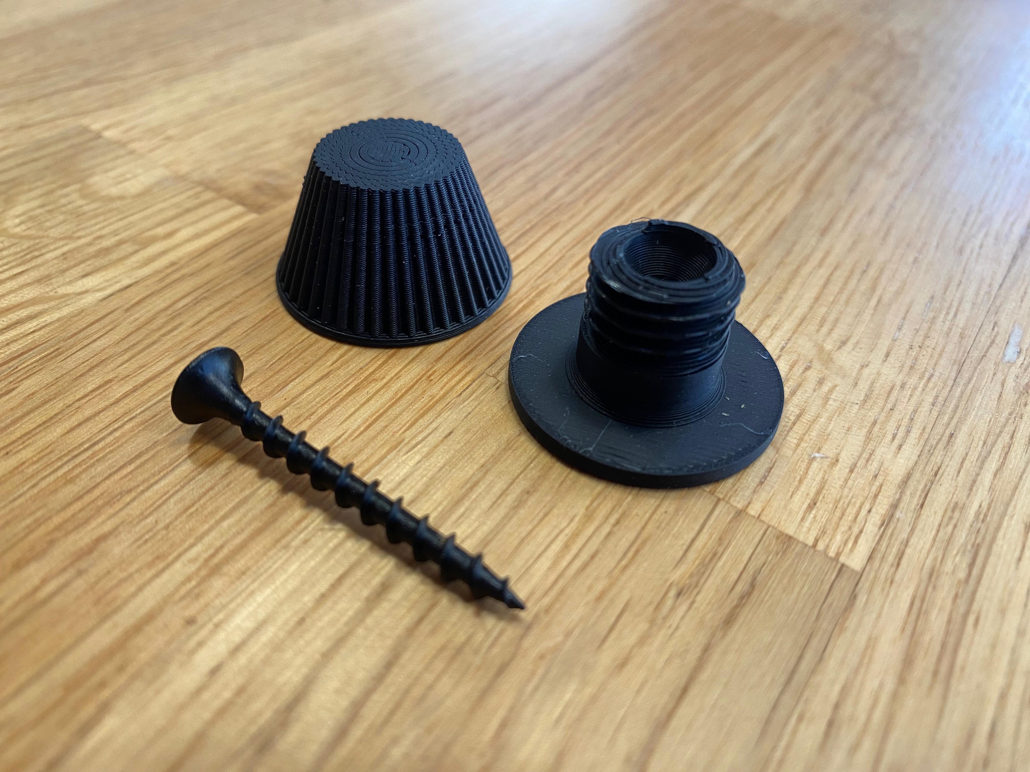
To attach the mesh, I designed some thumb turn eyelets in OpenSCAD, and 3D printed them in PLA.

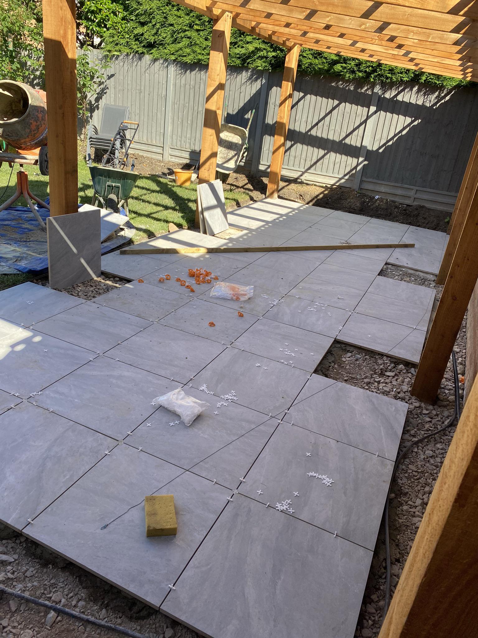
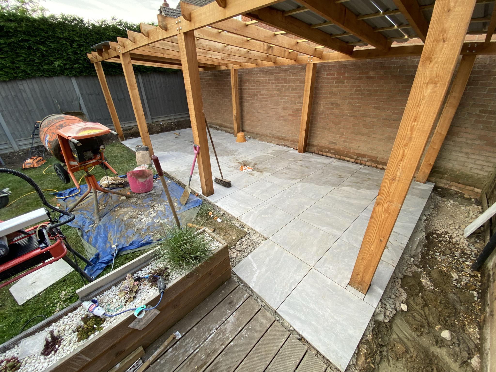
Floor
2021
Lessons learnt
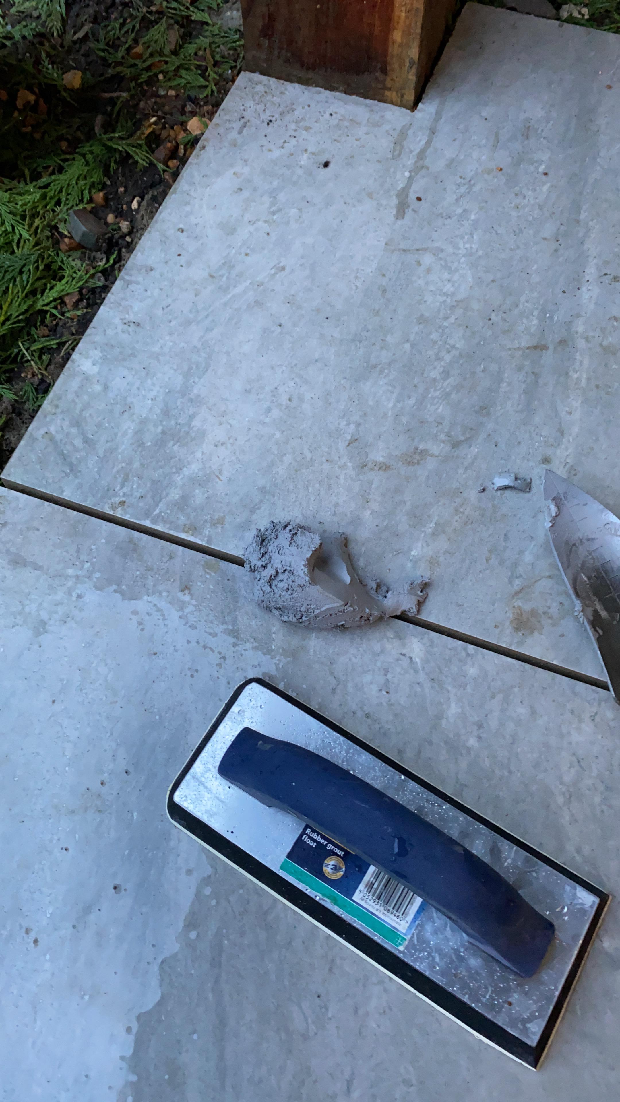
- Don’t bother with porcelain tiles
- …if you do, make a screed
With the help of my Dad, Brother, we shifted around 12 tonnes of dirt and various aggregates to make a solid base for the floor. We used a rented cement mixer, which made the job much easier.
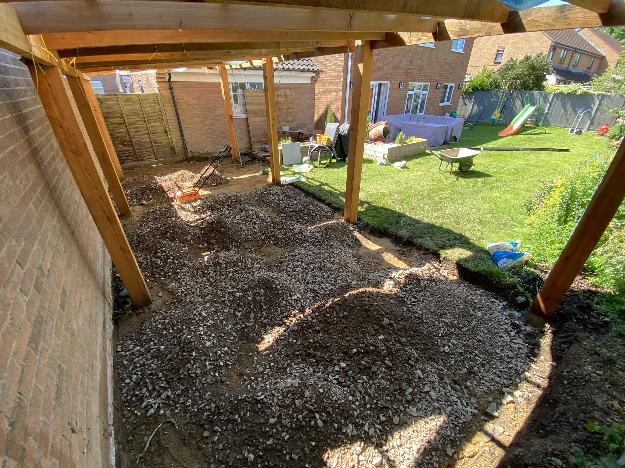
I used MOT type 2 as a base, compacted in layers with a friend’s electric plate compactor. This compactor was terrible, I had to “surf” it to get it to move. A petrol one would have been better.
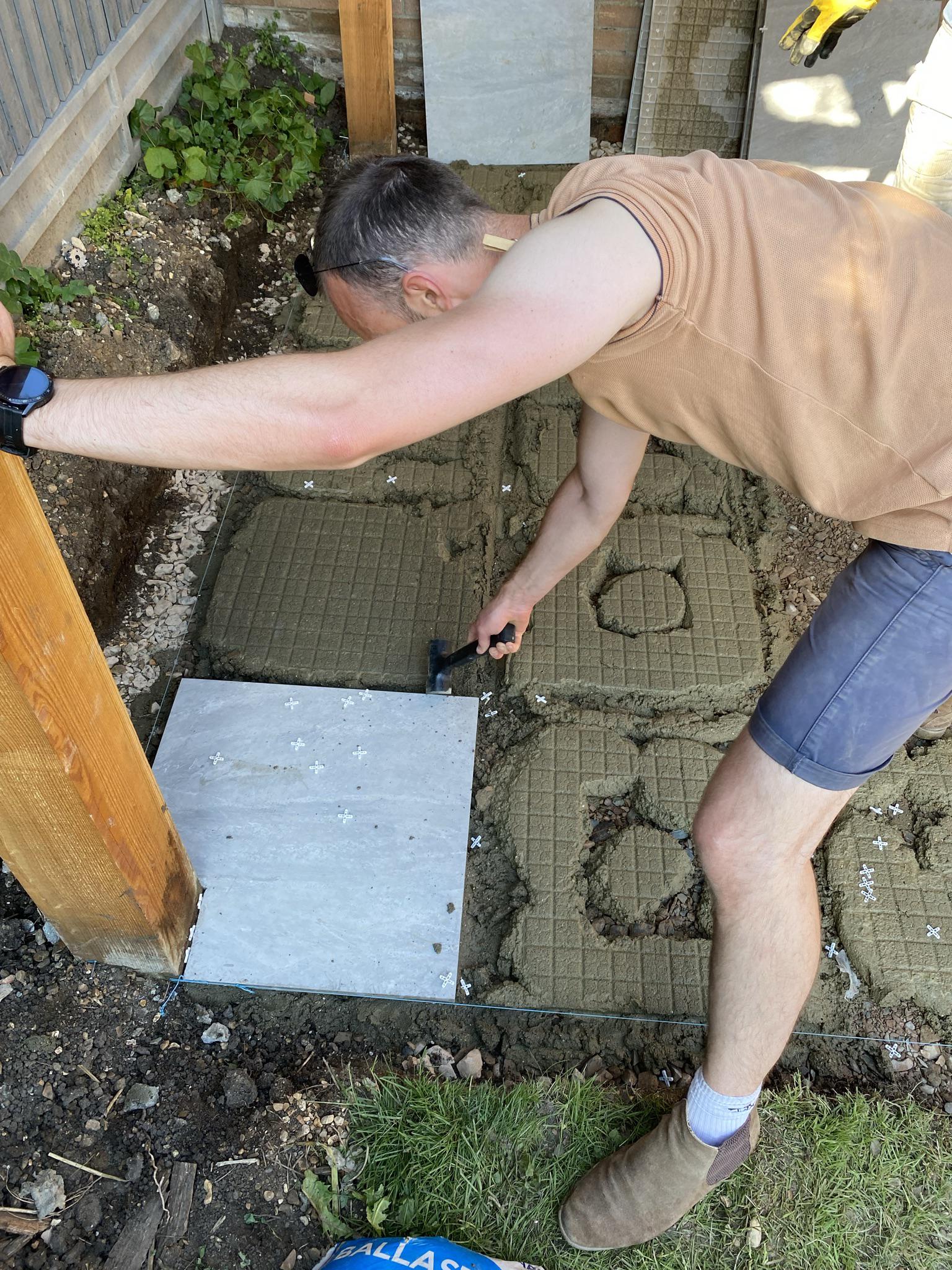
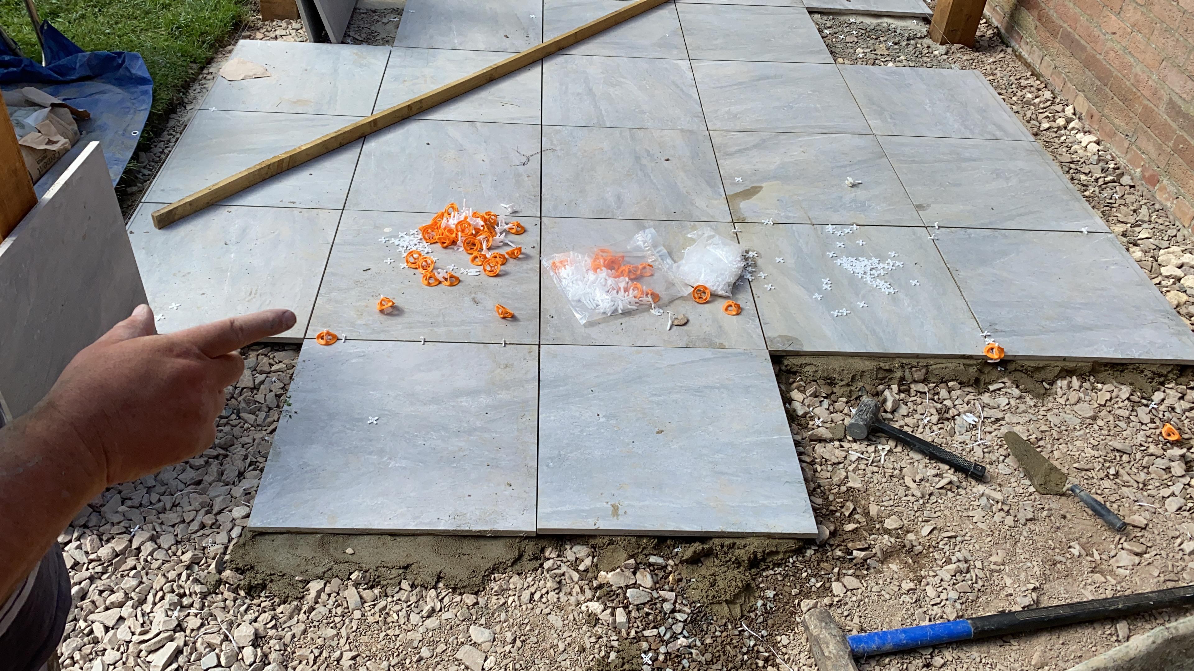
We mixed some 4:1 cement and sharp sand to bed the tiles in using 5 blobs per tile. This was a big mistake! I should have laid a screed to provide a flat base upon which to use tile adhesive as I had porcelain tiles. Given the precise and sharp edges, any unevenness in the base would lead to obvious lipping between tiles.
I really should have used standard paving slabs, which would have been much more forgiving.
Luckily, my brother had a knack for levelling the tiles, and became known as the great tile whisperer. I have no idea what he was whispering to the tiles, but it worked!
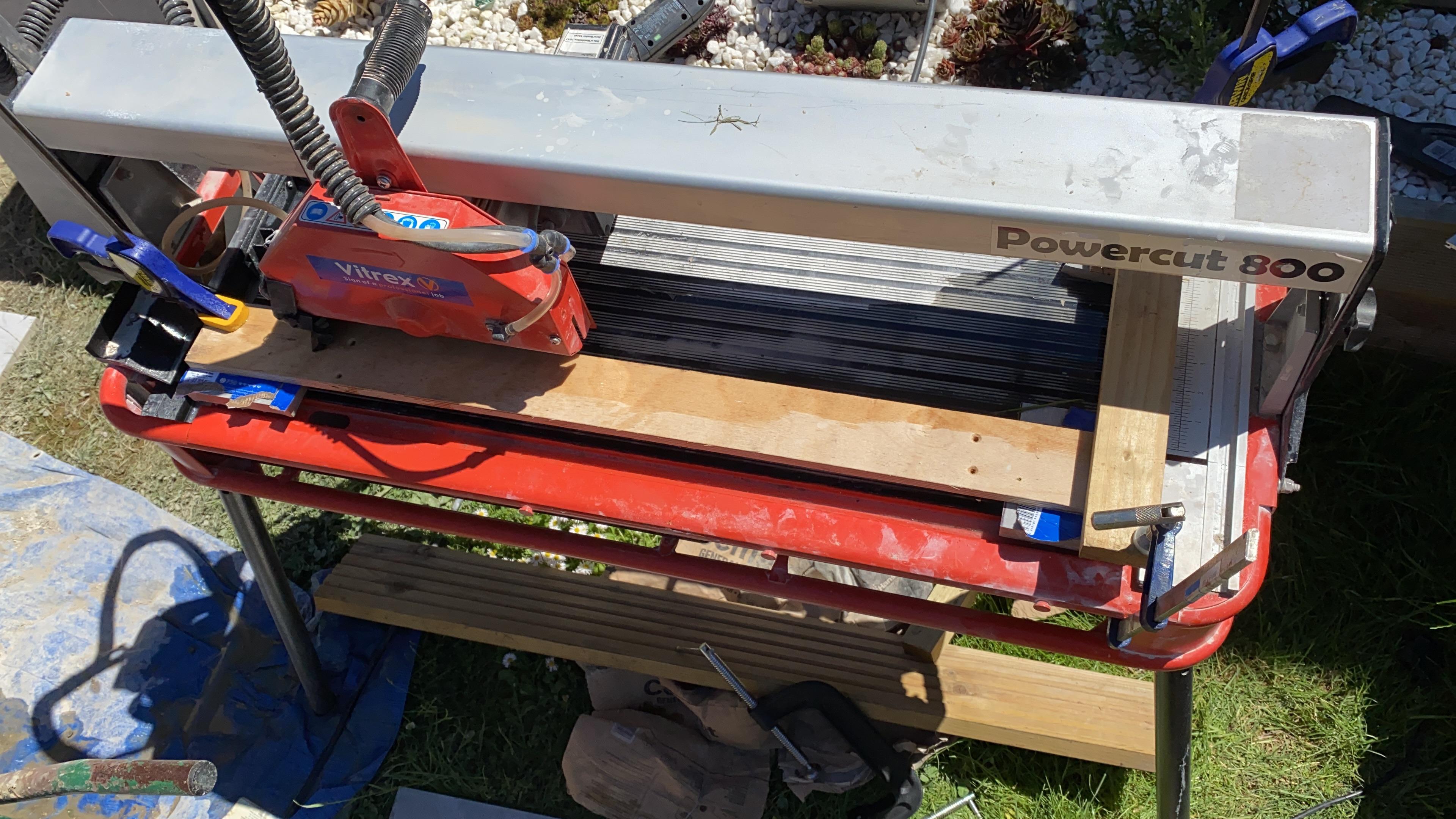
I borrowed a water-cooled diamond sliding tile cutter from a friend – this was essential for sharp cuts without chipping the edges – my angle grinder with a diamond blade was absolutely useless.
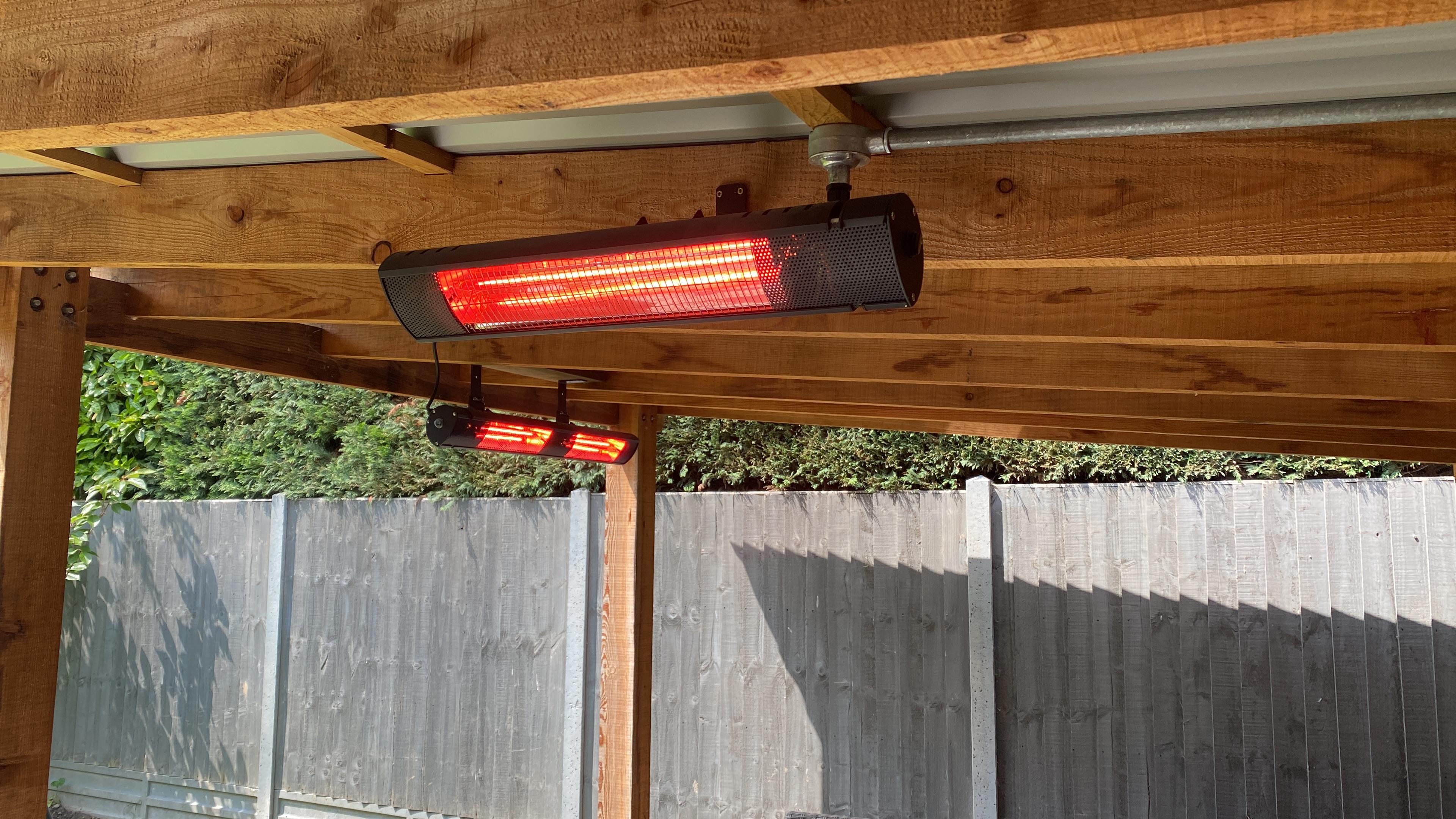
Lighting, heating & power
2023
When doing the groundwork for the floor, I laid some 6mm2 SWA cable to the consumer unit in the house. I arrived at 6mm2 after consulting table 4D2A in the IEC 7671 wiring regulations, given the 25m cable length and 32A breaker. This is to allow a 3KW and 2KW heater to be run at the same time, with enough left over for whatever else like the fridge, lights and kettle.
The garage consumer unit, some sockets and heater spurs were installed in the “secret” electrical cupboard mentioned earlier.
As for the lighting, I chose Philips Hue outdoor light strips and also E14 bulbs6 I had left over from our old house.
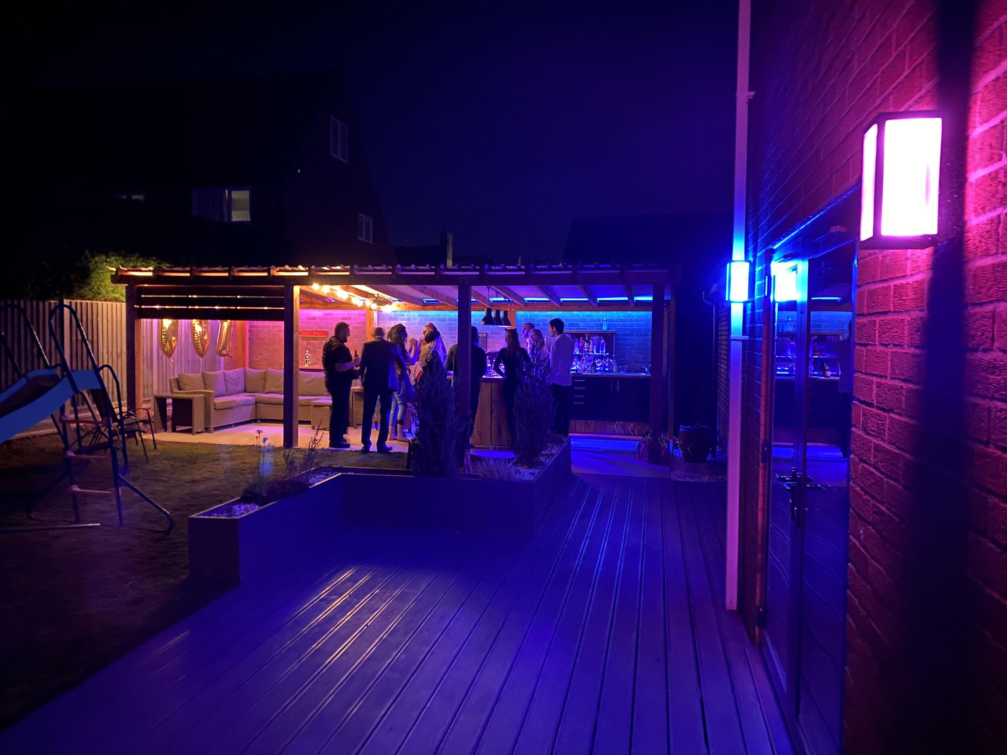
Where wiring would otherwise be exposed, I used galvanised steel conduit to give the heating and lighting a robust, industrial look.
From when Hue was new, made from metal and glass, not plastic! The Hue hub was also local only, no cloud or account required. We have regressed. ↩︎
Conclusion
Throughout building, my most useful tool was the 18ga (and 16ga) nail gun. It made things much faster and less awkward, often eliminating the need for clamps and allowing a better surface finish. The circular saw was also essential, and the 3D printer came in handy for a lot of random fixtures and jigs.
We’re super happy with the bar. It was a lot of work but totally worth it! I made a few mistakes along the way but I hope you won’t make the same ones if you’re thinking of building something similar.
Thanks for reading! If you enjoyed this article or have comments, please consider sharing it on Hacker news, Twitter, Hackaday, Lobste.rs, Reddit and/or LinkedIn.
You can email me with any corrections or feedback.
Tags:
Related:

