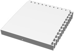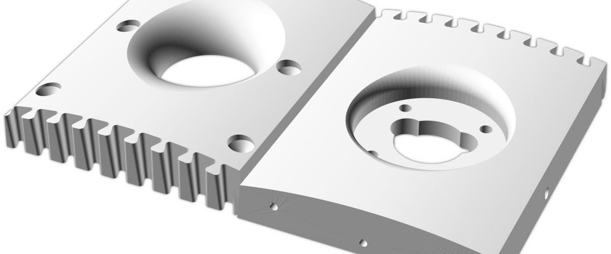
3D printing giant things with a python jigsaw generator
I really like the idea of a fully automated pipeline1 when I build anything – it’s highly satisfying to see a machine do all the work for you. Combine this with parametric design, and it makes iteration and customisation a breeze. My flagship example is my recent speaker project.
With the previous speaker project I was literally at the margins for the largest speaker I could comfortably make with my 3D printer – without significantly more work splitting up the design. I was looking to see what large format printers were out there – there are a handful but they’re expensive and possibly not as capable as what I have now.
Then I happened to watch a video where Richard from RMC 3D prints an entire arcade machine using a farm of relatively small printers. After creating the model, 2 he split it into macro layers, each of which where split into smaller parts that had a dovetail slot for assembly. It apparently worked really well.3
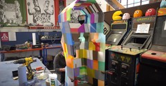
What if I could automate this process?
In the last article about speaker design I mention the possibility of floor-standing speakers, glossing over the fact that I’d have to segment the print. If I constrained the system to work on panel-type designs such as this speaker system, it would be quite straightforward to implement.
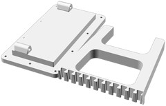
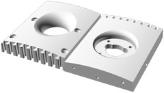
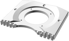
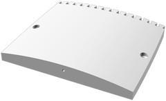
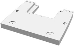
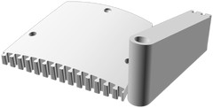
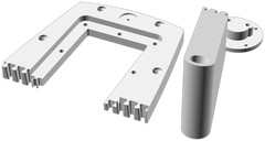
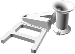
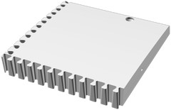
I already wrote a system to place the parts nested on individual beds; I decided to adapt that code to also be able to split up panels into a what is effectively a jigsaw. I could use dovetail joins to do this, allowing something that can be easily glued and requiring no extra parts like dowels.
If I got it right, it would divide the parts through complex geometry without a significant impact on the final finish.
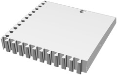
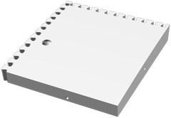
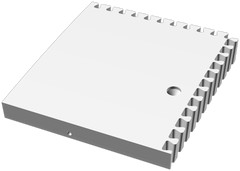
The dovetail profile
Dovetail joins are a traditional way to join wood together. They’re generally used for strength, but also aesthetics. They can be manually cut, or made using a handheld router (using a jig) or CNC router.
The strength comes from the tightening/wedging effect when pulling the join apart. If the dovetail is tapered, the join can also tighten when it aligns too – this is highly desirable for gluing, as it means the glue will not be scraped away.
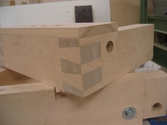
I took a look at some dovetail implementations in OpenSCAD, but none had all the features I needed.
I desired an approach that would subtract plastic once such that we end up with a fully mated join straight away. In theory this would simplify the design such that the two parts don’t need 2 separate, complicated and overlapping negatives to subtract.
This calls for a thin “shell” type structure, like a zig-zagging ribbon; even better it should be tapered!
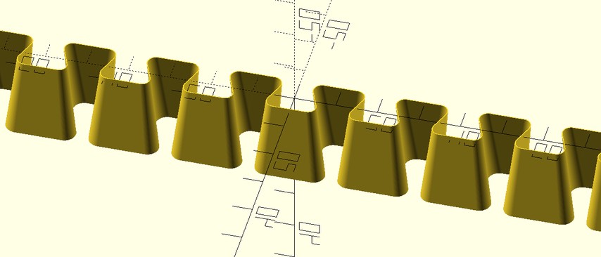
OpenSCAD, being CSG based is not well suited to creating thin shells, so this can be a bit awkward to do.
Deriving the geometry
Here is the deconstruction of the dovetail profile, after a few iterations to remove artefacts and optimise.
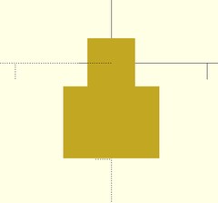
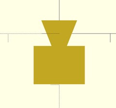
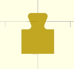
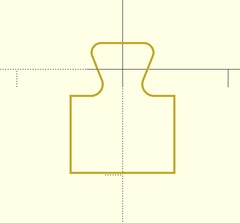
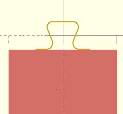
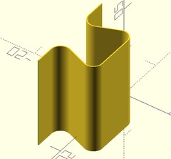
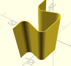
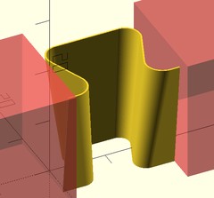
Interestingly, step 8 was originally done as an intersection, but I found that it absolutely destroyed OpenSCAD performance. You’re talking one frame every few minutes instead of dozens per second!

I didn’t remove the interfering edges at first – see the hanging artefacts screenshot later on. I was confused and thought it was a bug at first, until I examined the 3D tooth again.


Here’s the code that does exactly what you see above, complete with annotations to show what step corresponds to what. Only 68 lines!
| |
Test prints
I made several test prints to find what felt like the right set of parameters for the ratios described above. I settled on quite a small tooth, as it would reduce the size of any artefacts produced. Plus, the fit felt tighter.
In case you’re wondering, I found the 0.2mm interference fit that Richard used in the video worked best, leaving a bit of play and somewhere for the glue to go.
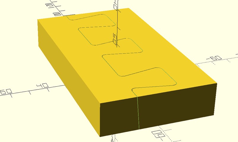
Performance was kept in check by limiting the number of faces ($fn=16) in the tooth code. This was a good compromise, smooth enough and reduces stress concentration sufficiently.4

I am a little concerned about the Z-fighting hat occurs when the parts are joined. Usually I make sure the parts intersect a little to avoid this. It looks fine, I’ll just hope I don’t have any manifolding issues later on for now.
I imagine! ↩︎
Edge artefacts
Sometimes the top part of a tapered tooth can be suspended in mid-air – this occurs when a boundary occurs at a tooth edge. This is a problem as it will cause spaghetti when printing, not to mention missing chunks in the final design.
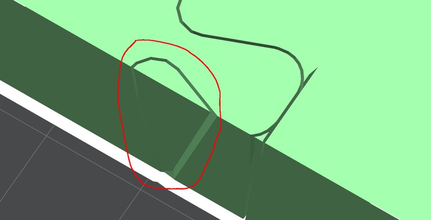
I realised I could at least detect and remove these artefacts in the (post-processing)5 code by looking for independent tiny fragments that aren’t touching the bed. I can at least then prevent the spaghetti; there will still be a hole in the design but I presume most of the time that can be addressed in the finishing step.
“We’ll fix it in post!” ↩︎
Automatically splitting up STLs
Now that I had geometry to create the joins in-place, I needed to automate the process so I can cut up an arbitrary design to fit on a given printer.
As I’ve mentioned, this only has to work on panels6 so I have the luxury of only having to operate in 2D and assume the parts are mainly flat and rectangular.
To automate it, I figured it would be far easier to do this (mostly) outside of OpenSCAD and operate on STLs directly. That way this system will work on 3D printed models from any CAD software.
I have already developed some part nesting software using rectpack and numpy-stl, so I decided to use that as a base.
The resulting code is straightforward. Here’s how it works:
- Load the STL file and find the bounding box of the model
- Rotate it so the aspect ratio matches the bed of the printer (and optionally, so the design is at its longest along the same axis as the printer bed)
- Calculate how m any sub-divisions are necessary on each axis to produce parts that will fit on the bed (margin of tooth size required)
- Execute an OpenSCAD template that will subtract the dovetail teeth from the model, translating the STL so each cut is in the right place
- Split those STLs into separate files with
slic3rcli - Remove any edge artefacts by looking for small objects
OK so technically it’s not arbitrary, but it’s close! I had to get that XKCD reference in there somewhere. ↩︎
Results
I refactored by nesting code to allow adding the dovetail splitting code without causing a mess. After a lot of debugging I ran the code, only to be disappointed! It took 4 hours to run per operation, only to fail with these errors:
ERROR: CGAL error in CGALUtils::applyBinaryOperator difference: CGAL ERROR: assertion violation!ERROR: The given mesh is not closed! Unable to convert to CGAL_Nef_Polyhedron
OpenSCAD uses the CGAL library which is notoriously slow, and it can produce non-manifold meshes. The speaker design I made produces non-manifold STLs – I think they have holes in due to some OpenSCAD implementation issues, or something with my code.
Those errors above are likely to be caused by these non-manifold edges. What could I do? I didn’t want to get this far only to abandon the project. Luckily, recently OpenSCAD has integrated a new geometry library called manifold7 which is apparently several orders of magnitude faster and more robust.
I tried this using an unstable version of OpenSCAD with the --backend=manifold flag, and it worked! Not only did it work, but it computed the design in 223ms! This is a 64500x improvement.
I should try manifold with the rest of the design. Manifold seems to use more memory and is multi-threaded, so I’d have to modify my build scripts which currently build 16 parts at once – last time I tried it overwhelmed the system.
Anyway, after an evening of more hacking I got it properly integrated and behaving as expected. Here’s the previous speaker design with a bed size reduced to 200x200 – this means it could be printed on a Prusa i3!8
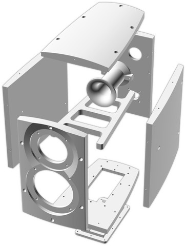
It seems to have worked exceptionally well. I like how the nesting algorithm has placed the split parts together as well to reduce required beds. This will decrease total printing time and effort. In one case (bed 17) the part did not fit in one bed, but was split so it could be.
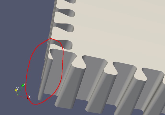
Looking at the corners, it seems quite common for the above to occur. As we know where the intersections of dovetail joins are, we could skip teeth to avoid the issue. That’s for another day though.
I’ve linked the code above. It expects slic3r, rectpack, openscad-nightly and numpy-stl, as well as the dovetail.scad to be in lib/. I hacked it from 2 files, so it might need a few fixes to work.
Thanks to Olivier Chafik https://ochafik.com/ and others. ↩︎
Of course you could go the other way and print something giant on my 256x256 X1C bed, but then I’d be doing the title justice! ↩︎
Conclusion
The chosen profile is self-aligning, and increases the surface area for glue to bond. It’s easy to align against a straight edge if a silicone mat is used to prevent the glue from sticking to things it shouldn’t.
This has successfully unlocked a floor-standing speaker design using this method in the near future, after validating the design and experimenting with different adhesives and finishes.9 Or, perhaps I will repackage my small MDF subwoofer I built a few years ago.
I could have implemented this as part of the speaker design with about 12 special cases. This way I could also avoid edge artefacts and more carefully place the joins to avoid detailed geometry. However, this is less transferable to other designs and less elegant in my opinion.
With some improvements, I could have the best of both worlds:
- Give it the ability to vary the part division location to target more plastic for stronger and practical joins
- Skip teeth where joins intersect as mentioned above
- Skip teeth near voids/edges (this and the above could be done by iteratively removing teeth to see if fragments are also removed, with perturbation to avoid thin features)
To do this, and possibly to replace the use of numpy-stl and/or OpenSCAD, I could look into trimesh which can do a lot more.
I’m confident the assembled parts will allow for a flawless finish if filled and sanded, given my experience with the last project.
I have made the code available linked to this post for the time being – I will happily package this up properly if there’s significant interest. I’m curious as to what other people could do with the idea or variant thereof.
I had assumed I’d want to mill the next speaker, but my last project was such as success I will happily take the advantages of 3D printing! ↩︎
Thanks for reading! If you enjoyed this article or have comments, please consider sharing it on Hacker news, Twitter, Hackaday, Lobste.rs, Reddit and/or LinkedIn.
You can email me with any corrections or feedback.
Tags:
Related:
